

Introduction: Simple & Smart Robotic Arm Using Arduino !!!
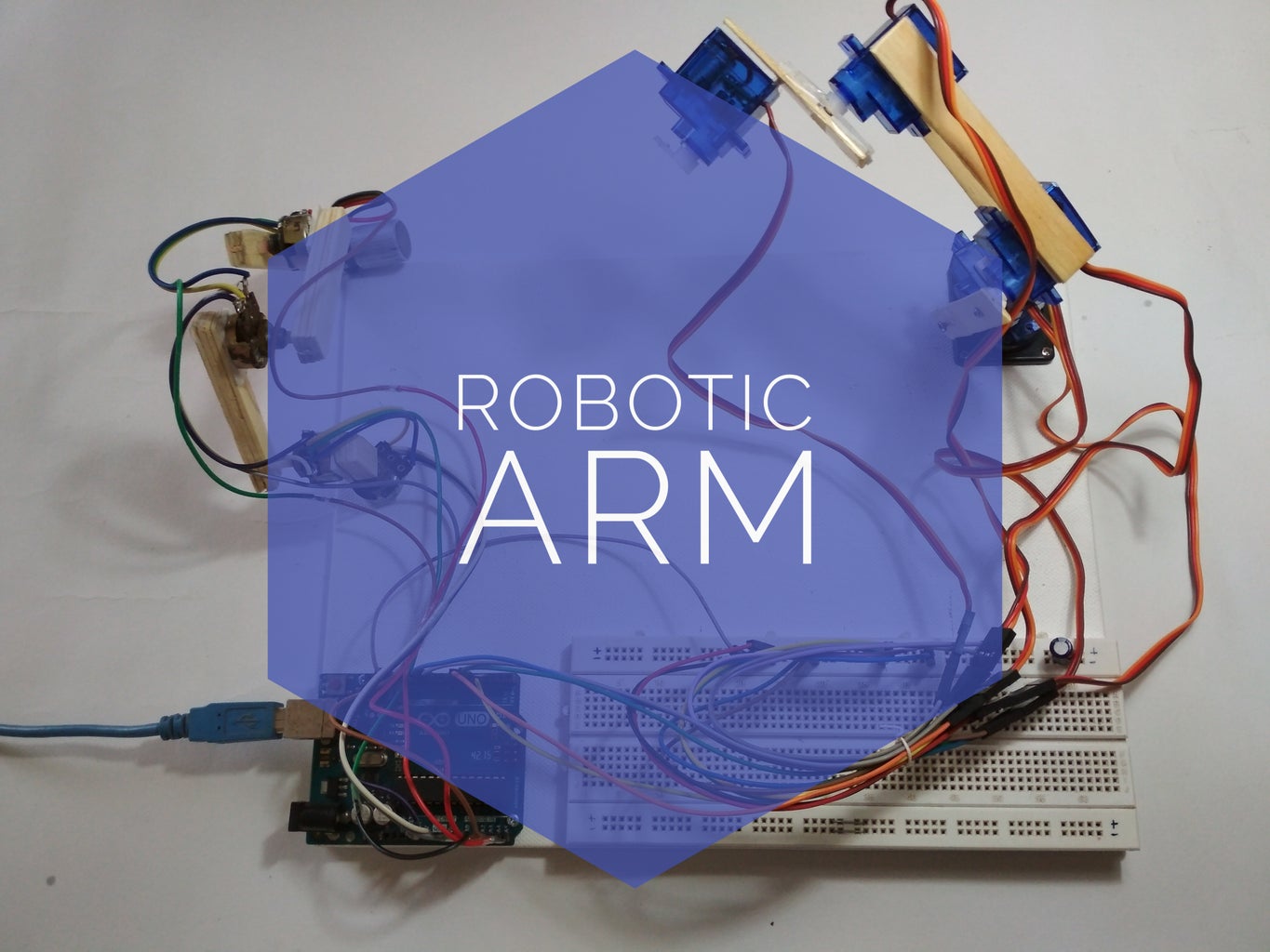


In this instructable I will be making a simple robotic arm. That will be controlled using a master arm. The arm will remember moves and play in sequence. The concept isn't new I got the Idea from "mini robotic arm -by Stoerpeak" I wanted to make this for a long time, but back then I was totally noob and had no knowledge about programming. Now finally I am building one, Keeping it simple, cheap and sharing it with you all.
So lets get started....
Step 1: Things You'll Need :-
Here is a list of things you will need:-
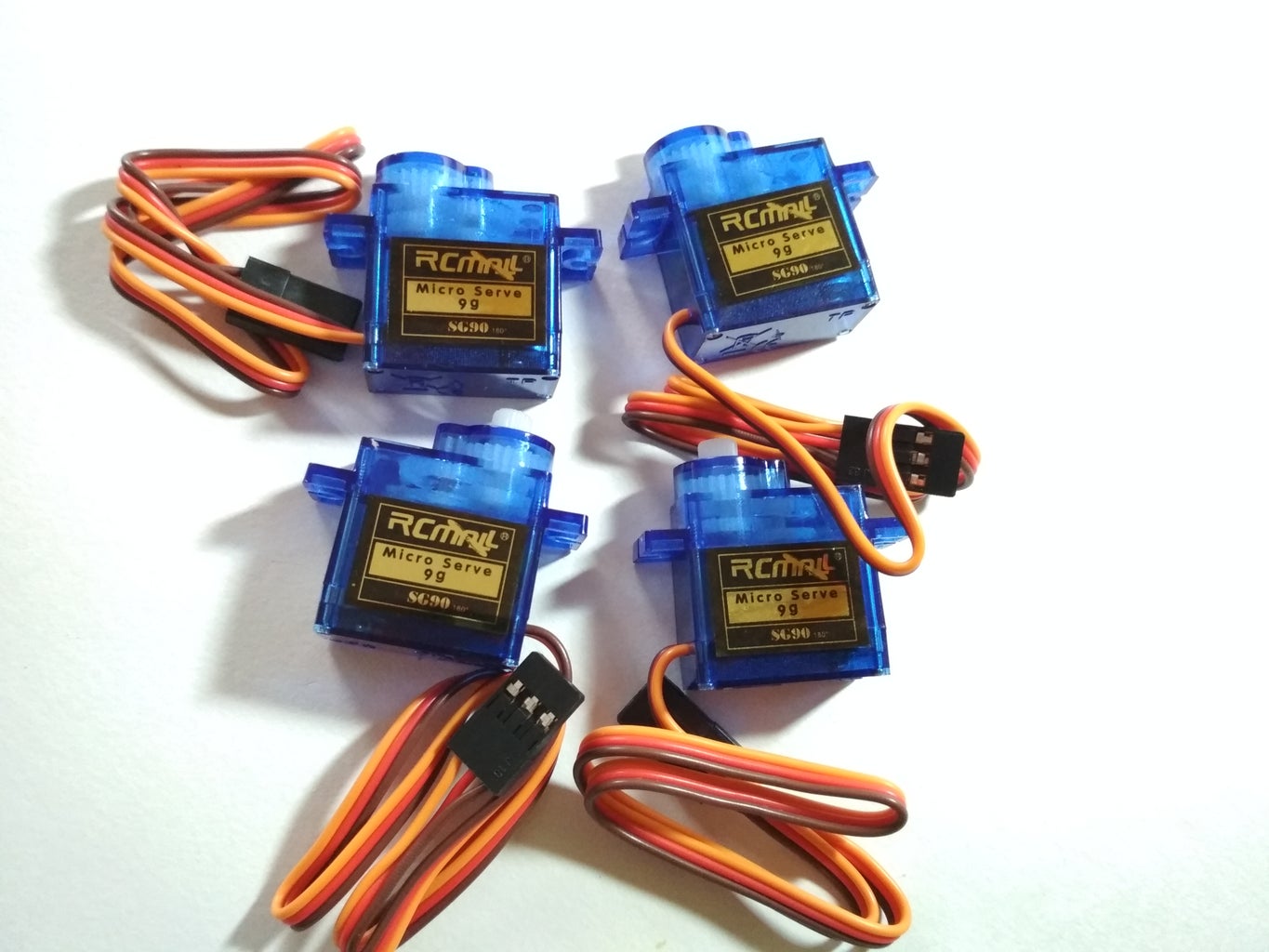
1. Servo motors x 5 (Amazon US / Amazon UK / Amazon IN)
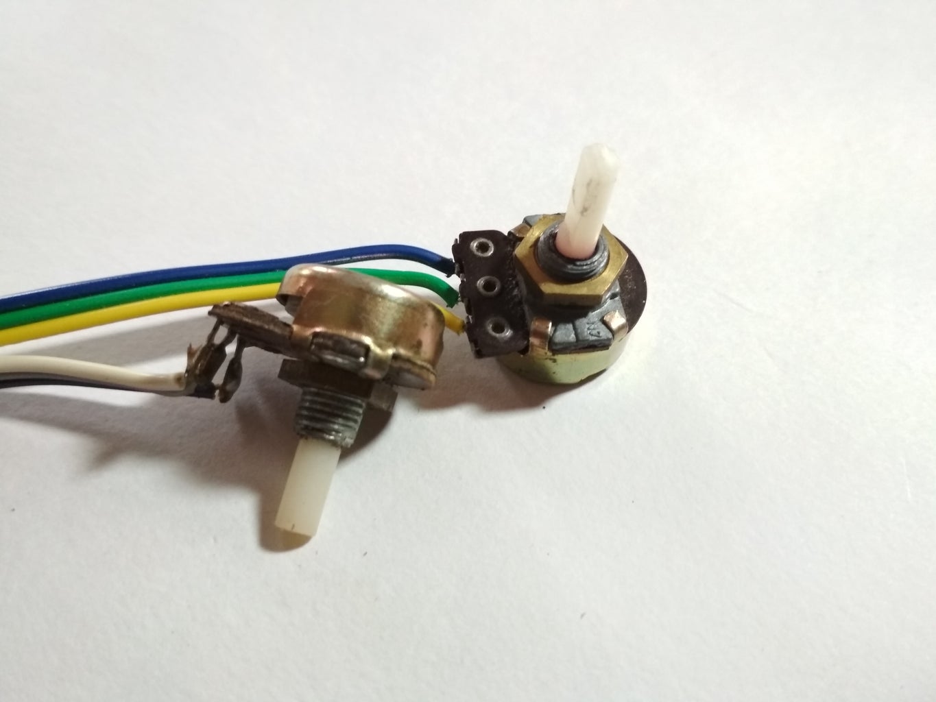
2. Potentiometers x 5 (Amazon US / Amazon UK / Amazon IN)
3. Arduino UNO. (Amazon US / Amazon UK / Amazon IN)
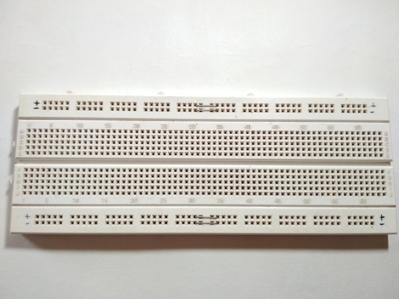
4. Breadboard. (Amazon US / Amazon UK / Amazon IN)
5. 5V 2A Adaptor. (Amazon US / Amazon UK / Amazon IN)
6. Cardboard/Wood/Sun-board/acrylic whatever is available or easy to find.
And you will also need Arduino IDE installed.
Step 2: Making the Arm :-
Here I have used Popsicle sticks to make the arm. You can use any material that is available to you. And you can try different mechanical designs to make an even better arm. my design is not very stable.
I just used double-sided tape to stick the servos to the Popsicle stick and fasten them using screws.
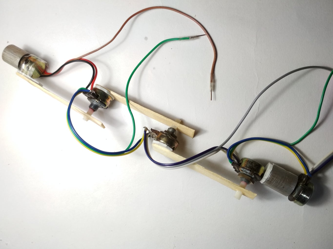
For the Master arm, I glued potentiometers to popsicle sticks and made an arm.
Referring to the pictures will give you a better idea.
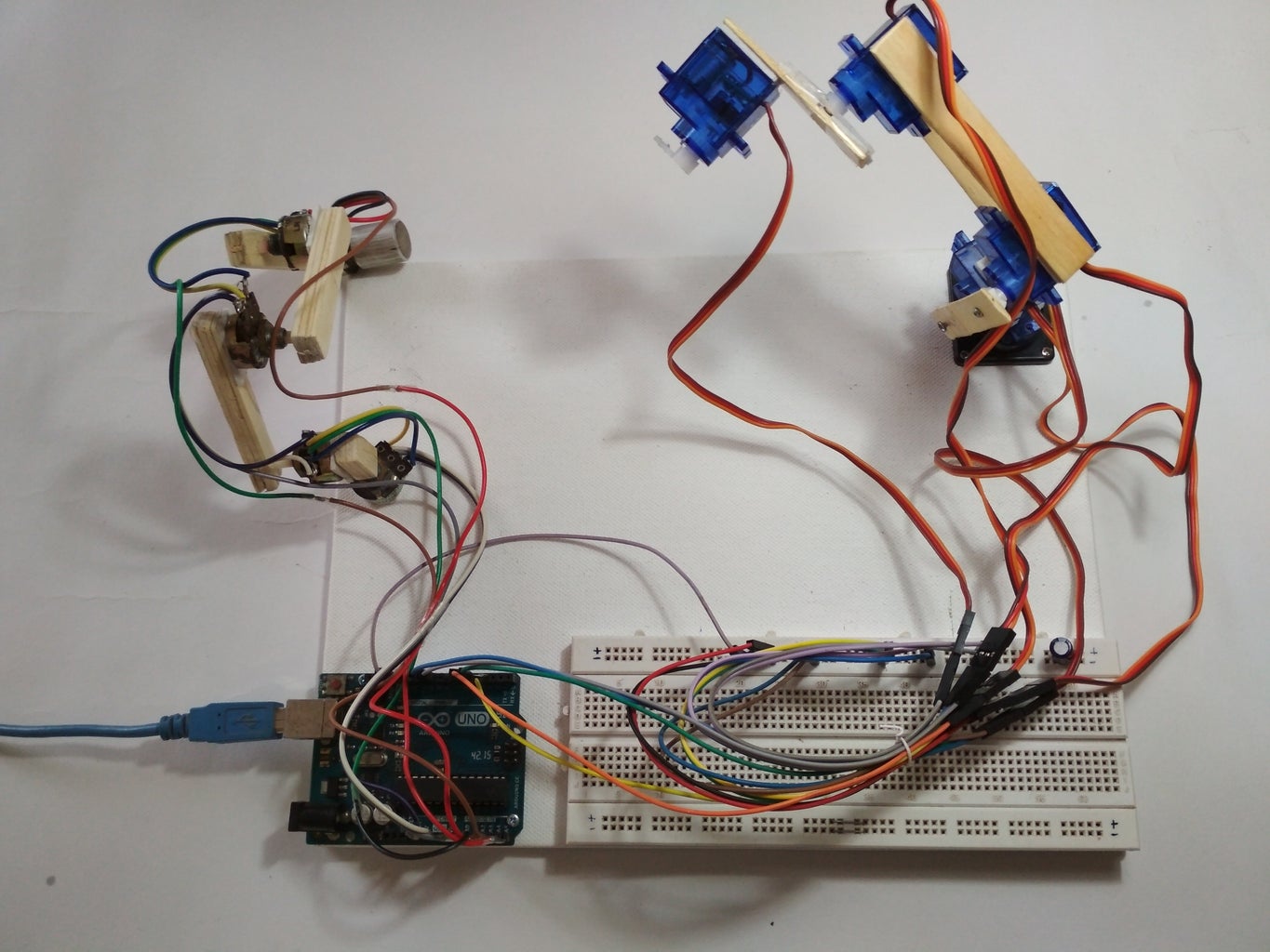
I have mounted everything on an A4 size canvas board used as a base.
Step 3: Making Connections :-

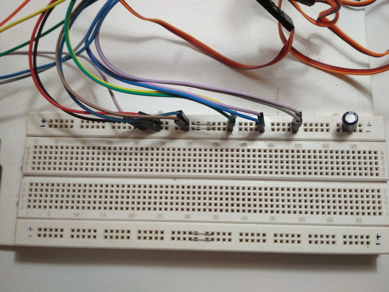
In this step, we will make all the necessary connections, Refer to the pictures above.
- First, connect all the servos in parallel to the power supply ( The Red wire to +ve and Black or Brown Wire to Gnd)
- Next, connect the signal wires i.e Yellow or Orange wire to the PWM pin of Arduino.
- Now connect the potentiometers to +5v and Gnd of Arduino in parallel.
- Connect the middle terminal to the Analog pin of Arduino.
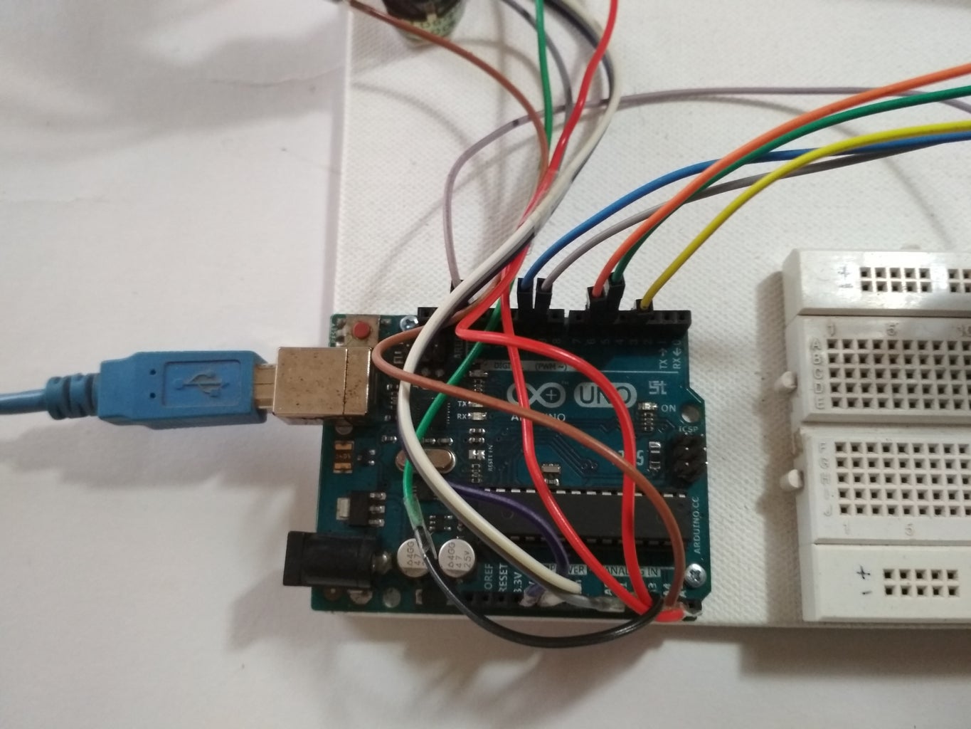
Here Digital Pins 3,5,6,9 & 10 are used for controlling the servos
Analog Pins A0 to A4 are used for Input from Potentiometers.
The servo connected to pin 3 will be controlled by a potentiometer connected to A0
Servo connected to pin 5 will be controlled by pot on A1, and so on...
Note:- Even though Servos are not powered by Arduino, Make sure to connect the GND of the servos to Arduino or else the arm won't work.
Step 4: Coding :-

The Logic of this code is fairly simple the values of potentiometers are stored in an array the records are then traversed using a for loop and the servos do the steps as per the values. You can check out this tutorial I used for reference "Arduino Potentiometer Servo Control & Memory"
Code:- (Downloadable file attached bellow.)
- First, we will declare all the necessary variables globally so we can use them throughout the program. No special explanation is needed for this.
#include <Servo.h>

//Servo Objects
Servo Servo_0;
Servo Servo_1;
Servo Servo_2;
Servo Servo_3;
Servo Servo_4;

//Potentiometer Objects
int Pot_0;
int Pot_1;
int Pot_2;
int Pot_3;
int Pot_4;

//Variable to store Servo Position
int Servo_0_Pos;
int Servo_1_Pos;
int Servo_2_Pos;
int Servo_3_Pos;
int Servo_4_Pos;

//Variable to store Previous position values
int Prev_0_Pos;
int Prev_1_Pos;
int Prev_2_Pos;
int Prev_3_Pos;
int Prev_4_Pos;

//Variable to store Current position values
int Current_0_Pos;
int Current_1_Pos;
int Current_2_Pos;
int Current_3_Pos;
int Current_4_Pos;


int Servo_Position; //Stores the angle
int Servo_Number; //Stores no of servo

int Storage[600]; //Array to store data (Increasing array size will consume more memory)
int Index = 0; // Array index starts from 0th position
char data = 0; //variable to store data from serial input.
- Now we will write a setup function, where we set pins and their functions. This is the main function that executes first.
void setup()
{
  Serial.begin(9600); //For Serial communication between arduino and IDE.

  //Servo objects are attached to PWM pins.
  Servo_0.attach(3);
  Servo_1.attach(5);
  Servo_2.attach(6);
  Servo_3.attach(9);
  Servo_4.attach(10);

  //Servos are set to 100 position at initialization.
  Servo_0.write(100);
  Servo_1.write(100);
  Servo_2.write(100);
  Servo_3.write(100);
  Servo_4.write(100);

  Serial.println("Press 'R' to Record and 'P' to play");
}
- Now we have to read the values of potentiometers using Analog Input pins and map them to control servos. For this we will define a function and name it Map_Pot();, you can name it anything you want it is a user-defined function.
void Map_Pot()
{
 /* The servos rotate at 180 degrees
    but to using it to limits is not
    a good idea as it makes the servos buzz continuously
    which is annoying so we limit the servo to move
    between: 1-179 */

   Pot_0 = analogRead(A0);               // Read input from pot and store it in the Variable Pot_0.
   Servo_0_Pos = map(Pot_0, 0, 1023, 1, 179); //Map servos as per the value between 0 to 1023
   Servo_0.write(Servo_0_Pos);           //Move the servo to that position.

   Pot_1 = analogRead(A1);
   Servo_1_Pos = map(Pot_1, 0, 1023, 1, 179);
   Servo_1.write(Servo_1_Pos);

   Pot_2 = analogRead(A2);
   Servo_2_Pos = map(Pot_2, 0, 1023, 1, 179);
   Servo_2.write(Servo_2_Pos);

   Pot_3 = analogRead(A3);
   Servo_3_Pos = map(Pot_3, 0, 1023, 1, 179);
   Servo_3.write(Servo_3_Pos);

   Pot_4 = analogRead(A4);
   Servo_4_Pos  = map(Pot_4, 0, 1023 , 1, 179);
   Servo_4.write(Servo_4_Pos);
}
- Now we will write the loop function:
void loop()
{
   Map_Pot();  //Function call to read pot values

   while (Serial.available() > 0)
   {
     data = Serial.read();
     if (data == 'R')
     Serial.println("Recording Moves...");
     if (data == 'P')
     Serial.println("Playing Recorded Moves...");
   }

  if (data == 'R') //If 'R' is entered, start recording.
  {

    //Store the values in a variable
    Prev_0_Pos = Servo_0_Pos;
    Prev_1_Pos = Servo_1_Pos;
    Prev_2_Pos = Servo_2_Pos;
    Prev_3_Pos = Servo_3_Pos;
    Prev_4_Pos = Servo_4_Pos;

    Map_Pot();  // Map  function recalled for comparison

    if (abs(Prev_0_Pos == Servo_0_Pos)) // absolute value is obtained by comparing
    {
      Servo_0.write(Servo_0_Pos); // If values match servo is repositioned
      if (Current_0_Pos != Servo_0_Pos)  // If values don't match
    {
        Storage[Index] = Servo_0_Pos + 0; // Value is added to array
        Index++;  // Index value incremented by 1
      }
      Current_0_Pos = Servo_0_Pos;
    }

    /* Similarly the value comparison is done for all the servos, +100 is added every for entry
       as a differential value. */

    if (abs(Prev_1_Pos == Servo_1_Pos))
    {
      Servo_1.write(Servo_1_Pos);
      if (Current_1_Pos != Servo_1_Pos)
      {
        Storage[Index] = Servo_1_Pos + 100;
        Index++;
    }
     Current_1_Pos = Servo_1_Pos;
   }


   if (abs(Prev_2_Pos == Servo_2_Pos))
   {
     Servo_2.write(Servo_2_Pos);
     if (Current_2_Pos != Servo_2_Pos)
     {
       Storage[Index] = Servo_2_Pos + 200;
       Index++;
     }
    Current_2_Pos = Servo_2_Pos;
   }


   if (abs(Prev_3_Pos == Servo_3_Pos))
   {
     Servo_3.write(Servo_3_Pos);
     if (Current_3_Pos != Servo_3_Pos)
     {
       Storage[Index] = Servo_3_Pos + 300;
       Index++;
     }
     Current_3_Pos = Servo_3_Pos;
   }
   if (abs(Prev_4_Pos == Servo_4_Pos))
   {
     Servo_4.write(Servo_4_Pos);
     if (Current_4_Pos != Servo_4_Pos)
     {
      Storage[Index] = Servo_4_Pos + 400;
      Index++;
     }
    Current_4_Pos = Servo_4_Pos;
  }

  /* Values are printed on serial monitor, '\t' is for displaying values in tabular format */
  Serial.print(Servo_0_Pos);
  Serial.print(" \t ");
  Serial.print(Servo_1_Pos);
  Serial.print(" \t ");
  Serial.print(Servo_2_Pos);
  Serial.print(" \t ");
  Serial.print(Servo_3_Pos);
  Serial.print(" \t ");
  Serial.println(Servo_4_Pos);
  Serial.print ("Index = ");
  Serial.println(Index);
  delay(50);
  }

  if (data == 'P') //IF 'P' is entered , Start playing recorded moves.
  {
    for (int i = 0; i < Index; i++) //Traverse the array using for loop
    {
      Servo_Number = Storage[i] / 100;  // Finds number of servo
      Servo_Position = Storage[i] % 100; // Finds position of servo

      switch(Servo_Number)
      {
        case 0:
             Servo_0.write(Servo_Position);
             break;

        case 1:
             Servo_1.write(Servo_Position);
             break;

        case 2:
             Servo_2.write(Servo_Position);
             break;

        case 3:
             Servo_3.write(Servo_Position);
             break;

        case 4:
             Servo_4.write(Servo_Position);
             break;
       }
     delay(50);
   }
 }
}
- Once the code is ready, Now upload it to the Arduino board.
The Smart arm is ready to work. The function is not yet as smooth as the one made by Stoerpeak.
If you can make the code better or have any suggestions for me please let me know in the comment section.
With that been said, let's move on to testing...
Attachments

Step 5: Testing :-
After uploading the code to the board successfully, Open 'Serial Monitor' you can find it in the Tools option. When the Serial monitor starts the Arduino will reset. Now you can control the robotic arm using the master arm. But nothing is being recorded.
To start recording, Enter 'R' on the monitor now you can perform the moves you wish to record.
After the moves are done you have to enter 'P' in order to play the recorded moves. The servos will continue to perform the moves as long as the board is not reset.
If you like this instructable, do follow for more. Also, check out more blogs on our website.


