

Introduction: Optical Theremin With Arduino Uno


A theremin is an electronic instrument in which two high-frequency oscillators control tone while the musicians hand movements control the pitch.
In this Instructable, we'll build a similar instrument, in which hand movements control the amount of light that the instrument's sensors receive, and that light measurement is converted into a resulting pitch from a buzzer.
Parts you'll need:
Step 1: Connect to Power
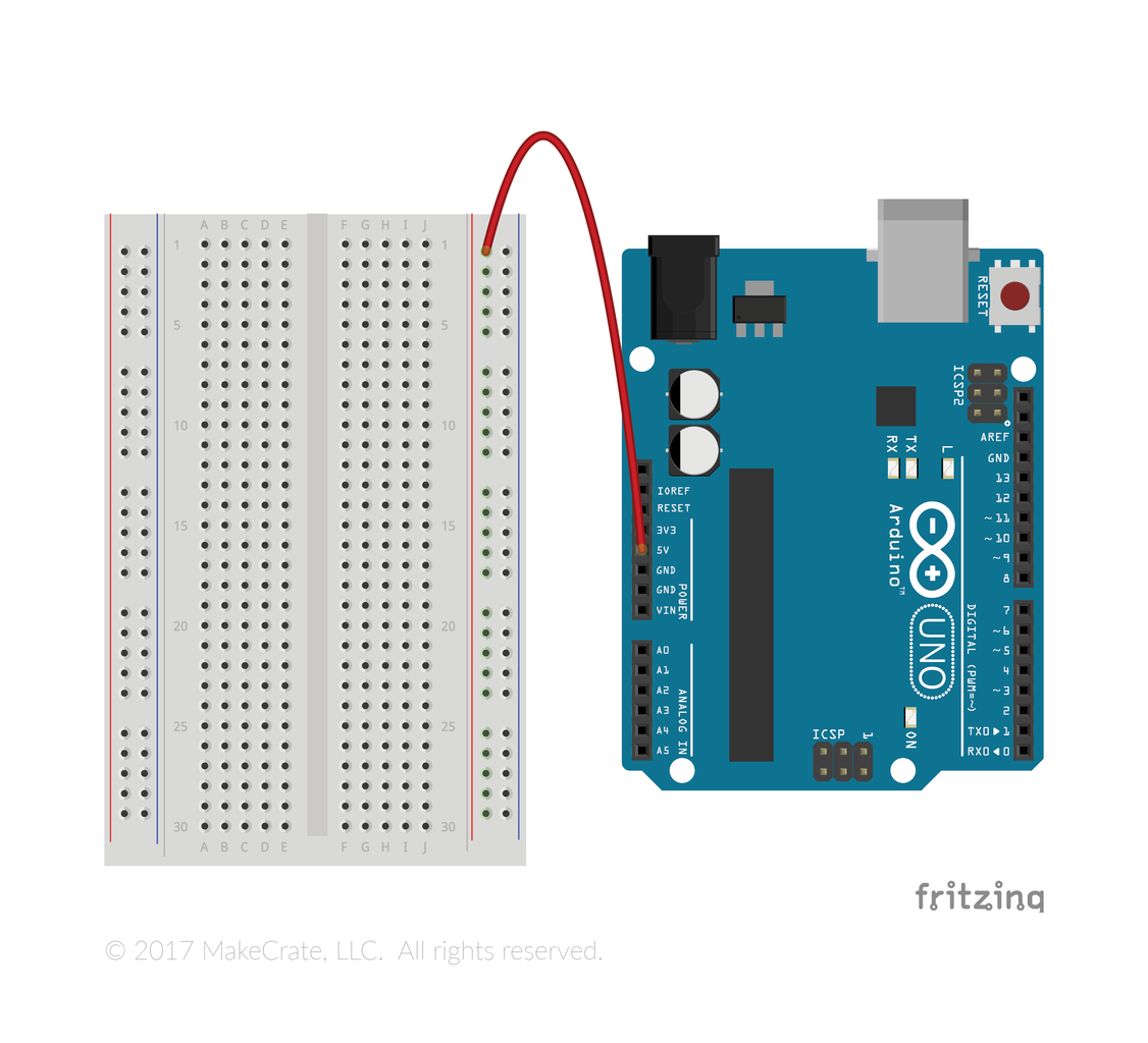
Start by connecting your breadboard's positive row to the 5V pin on the Arduino Uno.
Step 2: Connect to Ground

Then connect one of the GND pins to the negative line on your Arduino.
Step 3: The Buzzer

Insert your buzzer. It likely has a longer leg, or a small "+" sign on the top. Keep track of which side the longer leg or "+" sign are on.
Step 4: Ground the Buzzer

Connect the shorter leg of the buzzer to ground by inserting a wire in the same row as the shorter leg of the buzzer, and in the negative line on the breadboard.
Step 5: Power the Buzzer

Complete the buzzer circuit by connecting it to pin 12 on the Arduino.
Step 6: The Photoresistor

Start building the photoresistor circuit by inserting the photoresister so that it has one leg on each side of the channel down the middle of the breadboard.
Step 7: Connect the Photoresistor to Power
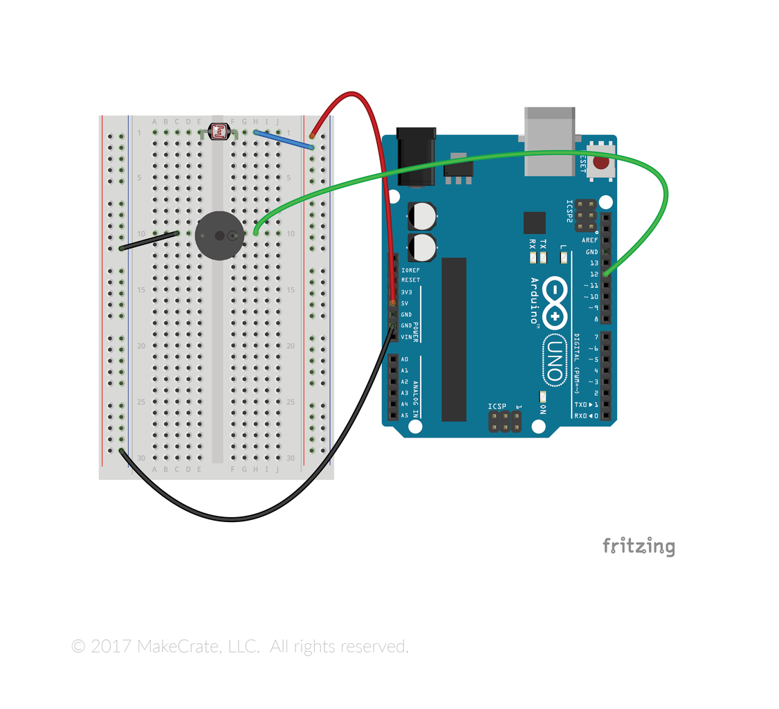
Use a wire to connect one leg of the photoresistor to the positive line on your breadboard that you connected to 5V earlier.
Step 8: Ground the Photoresistor

Connect the photoresistor's other leg to ground, connecting the 10K Ohm resistor to the negative line on your breadboard.
Step 9: Step 9: Connect the Photoresistor to the Arduino

We'll read the change in current through the resistor by connecting a wire between the photoresistor and its ground wire, back to pin A0 on the Arduino.
Step 10: Step 10: Write Your Code
int analogPin = A0;
int noteToPlay;
int sound; int speaker = 7;
void setup() {
Serial.begin(9600);
pinMode(analogPin, INPUT);
}
void loop() {
sound= analogRead(analogPin);
delay(200);
int notes[21] = {65, 73, 82, 87, 98, 110, 123, 131, 147, 165, 175, 196, 220, 247,262, 294, 330, 349, 392, 440, 494};
noteToPlay= map(sound, 0,1023, 0, 21);
tone(speaker, notes[noteToPlay]); delay(10);
}
Attachments

Step 11: Want More Projects Like This?

Check out MakeCrate!


