

Introduction: Internet Radio Using an ESP32


Dear friends welcome to another Instructable! Today we are going to build an Internet Radio device with a big 3.5” display using an inexpensive ESP32 board. Believe it or not, we can now build an Internet Radio in less than 10 minutes and with less than 30$. There is a lot to cover so, let’s get started!
A few months ago, I completed an Arduino FM Radio project which works great and looks even better in my opinion. If you want to see how I built this project you can read the Instructable here. The problem is that, although this radio looks cool it is not practical because I live in a small town in southern Greece and the big Greek radio stations I prefer to listen to, do not have transmitters around here. So, I listen to my favorite radios online on my laptop or tablet pc which is also not so practical. So, today I am going to build an Internet radio device in order to be able to listen to my favorite radio stations from all over the world!
As you can see, a first version of the project is ready on a breadboard. Let’s power it up. As you can see the project connects to the Internet and then streams music from predefined Radio Stations.
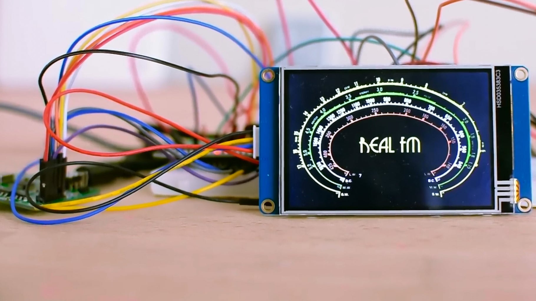
I have tuned in to the Real FM radio station from Athens and by using these buttons we can change the Radio Station we are listening to. I have saved my favorite radio stations to the memory of the ESP32 so I can access them easily. With this potentiometer, I can change the volume of the speaker. I display the Name of the Radio Station we are listening to on a big 3.5” display with a retro User Interface. The project works fine and it is very easy to build.
You can build the same project in less than 10 minutes but you need to have some experience. If this is your first project, consider building a simpler one first, to gain some experience. Check my Instructables for simple project ideas and when you are more comfortable with the Arduino the electronics come back to build this cool project. Let’s now start building our own Internet Radio.
UPDATE 6/6/2019
The noise issue has been solved by adding an isolator transformer. Check out the updated shematic diagram. Thanks!
Step 1: Get All the Parts

We are going to need the following parts:
- ESP32 ▶ http://educ8s.tv/part/ESP32
- MP3 decoder ▶ http://educ8s.tv/part/MP3Decoder
- Isolation Transformer ▶ http://educ8s.tv/part/AudioTransformer
- Amplifier ▶ http://educ8s.tv/part/PAM8403
- 3W speaker ▶ http://educ8s.tv/part/3WSpeaker
- 3.5" Nextion Display ▶ http://educ8s.tv/part/Nextion35
- Push Buttons ▶ http://educ8s.tv/part/Buttons
- Breadboard ▶ http://educ8s.tv/part/LargeBreadboard
- Wires ▶ http://educ8s.tv/part/Wires
The total cost of the project is around 40$ but if you don’t use a display the cost of the project is around 20$. Amazing stuff. We can build our own Internet radio with just 20$!
Step 2: ESP32 Board


The heart of the project is, of course, the powerful ESP32 board. If you are not familiar with it, the ESP32 chip is the successor of the popular ESP8266 chip we have used many times in the past. The ESP32 is a beast! It offers two 32 bit processing cores which operate at 160MHz, a massive amount of memory, WiFi, Bluetooth and many other features with a cost of around 7$! Amazing stuff!
Please watch the detailed review I have prepared for this board. I have attached the video on this Instructable. It will help understand why this chip will change the way we make things forever! One of the most exciting things about the ESP32 is that even though it is so powerful, it offers a deep-sleep mode which requires only 10μΑs of current. This makes the ESP32 the ideal chip for low power applications.
In this project, the ESP32 board connects to the Internet and then it receives MP3 data from the radio station we are listening to, and it sends some commands to the display.
Step 3: MP3 Decoder


The MP3 data is then sent to the MP3 decoder module using the SPI interface. This module uses the VS1053 IC. This IC is a dedicated hardware MP3 decoder. It gets the MP3 data from the ESP32 and converts it really fast into an audio signal.
The audio signal that it outputs at this audio jack is weak and noisy, so we need to clear it from the noise and amplify it. (If you are using headphones, the signal does not need to be cleared from noise or amplified.) That’s why I am using an Isolation transformer to clear the audio from the noise and a PAM8403 audio amplifier to amplify the audio signal and then send it to a speaker. I have also connected two buttons to the ESP32 just to change the MP3 Stream we are getting data from and a Nextion display to display the Radio station we are listening to.
Step 4: Nextion Display

I chose to use a Nextion display for this project since it is very easy to use. We only need to connect one wire to control it.
The Nextion displays are new kind of displays. They have their own ARM processor at the back which is responsible for driving the display and creating the graphical user interface. So, we can use them with any microcontroller and achieve spectacular results. I have prepared a detailed review of this Nextion display which explains in depth how they work, how to use them and their drawbacks. You can read it here , or watch the attached video.
Step 5: Connecting All the Parts


All we have to do now is to connect all the parts together according to this schematic diagram. You can find the schematic diagram attached here. The connection is straightforward.
There are two things to note though. The MP3 decoder module outputs a Stereo Signal but I am using only one audio channel in this project. In order to get the audio signal, I connected an audio cable to the audio jack of the module, and cut it to reveal four wires inside. I connected two of the wires. One of them is the GND and the other one is the audio signal of one of the two audio channels. If you wish you can connect both channels to the amplifier module and drive two speakers.
Each audio channel must go through the isolation transformer to clear any noise present before connecting to the amplifier.
To send data to the display, we only need to connect one wire to the TX0 pin of the ESP32. After connecting the parts, we have to load the code to the ESP32, and we have to load the GUI to the Nextion display.
To load the GUI to the Nextion display, copy the InternetRadio.tft file I am going to share with you to an empty SD card. Put the SD card into the SD card slot at the back of the display. Then power up the display, and the GUI will be loaded. Then remove the SD card and connect the power again.
After successfully loading the code, let’s power up the project. It displays the text “Connecting…” for a few seconds on the display. After connecting to the internet the project connects to a predefined radio station. The hardware is working as expected but now let’s see the software side of the project.
Step 6: The Code of the Project


First of all, let me show you something. The code of the project is less than 140 lines of code. Think about it, we can build an Internet Radio with a 3.5” Display with 140 lines of code, this is amazing. We can achieve all this using various libraries of course which contain thousands of lines of code. This is the power of Arduino and the Open source community. It makes things easy for makers.
In this project, I am using the VS1053 library for the ESP32 board.
At first, we have to define the SSID and the Password of the Wi-Fi network. Next, we have to save some Radio Stations here. We need the host URL, the path where the stream is located and the port we need to use. We save all this info into these variables.
char ssid[] = "yourSSID";            //  your network SSID (name) <br>char pass[] = "yourWifiPassword";   // your network password</p><p>// Few Radio Stations
char *host[4] = {"149.255.59.162","radiostreaming.ert.gr","realfm.live24.gr", "secure1.live24.gr"};
char *path[4] = {"/1","/ert-kosmos","/realfm","/skai1003"};
int   port[4] = {8062,80,80,80};
I have included 4 radio stations in this example.
In the setup function we attach interrupts to the buttons, we initialize the MP3 decoder module and we connect to the Wi-Fi.
void setup () {

   Serial.begin(9600);
   delay(500);
   SPI.begin();</p><p>   pinMode(previousButton, INPUT_PULLUP);
   pinMode(nextButton, INPUT_PULLUP);</p><p>   attachInterrupt(digitalPinToInterrupt(previousButton), previousButtonInterrupt, FALLING);
   attachInterrupt(digitalPinToInterrupt(nextButton), nextButtonInterrupt, FALLING);
   initMP3Decoder();
   connectToWIFI();
}
In the loop function, first of all, we check if the user has selected a different radio station than the one we are getting data from. If so, we connect to the new radio station else we get data from the stream and send them to the MP3 Decoder module.
<p>void loop() {<br>
      if(radioStation!=previousRadioStation)
      {
           station_connect(radioStation);
           previousRadioStation = radioStation;
      }

      if (client.available() > 0)
      {
        uint8_t bytesread = client.read(mp3buff, 32);
        player.playChunk(mp3buff, bytesread);
      }
}</p>
That’s all! When the user presses a button, an interrupt happens, and changes the value of a variable which tells which stream to connect to.
<p>void IRAM_ATTR previousButtonInterrupt() {</p><p>  static unsigned long last_interrupt_time = 0;
  unsigned long interrupt_time = millis();

 if (interrupt_time - last_interrupt_time > 200)
 {
   if(radioStation>0)
    radioStation--;
    else
    radioStation = 3;
 }
 last_interrupt_time = interrupt_time;
}</p>
To update the display, we simply send some commands to the serial port.
<p>void drawRadioStationName(int id)<br>{
  String command;
  switch (id)
  {
    case 0:  command = "p1.pic=2"; Serial.print(command); endNextionCommand(); break; //1940 UK Radio
    case 1:  command = "p1.pic=3"; Serial.print(command); endNextionCommand(); break; //KOSMOS     GREEK
    case 2:  command = "p1.pic=4"; Serial.print(command); endNextionCommand(); break; //REAL FM    GREEK
    case 3:  command = "p1.pic=5"; Serial.print(command); endNextionCommand(); break; //SKAI 100.3 GREEK
  }
}</p>
Now let’s take a look at the Nextion Display GUI. The Nextion GUI consists of a background picture and a picture which displays the name of the Radio Station. The ESP32 board sends commands to change the name of the radio station from the embedded images. It is very easy. Please watch the Nextion display tutorial I have prepared some time ago for more information. You can quickly design your own GUI if you wish and display more things on it.
As always you can find the code of the project attached in this Instructable.
Attachments

Step 7: Final Thoughts & Improvements


This project is very simple. I wanted a simple Internet Radio project skeleton to work with. Now that a first version of the project is ready we can add many features to it to improve it. First of all, I need to design an enclosure to house all the electronics.
In this book about the Most Beautiful Radios ever made there are very cool radios to choose from as an enclosure for this project. I think I am going to build an enclosure around this spectacular Art Deco radio. What do you think, do you like the looks of this radio or do you prefer something more modern? Do you have any other enclosure ideas? Also, do you like this Internet Radio project and what features do think we need to add to it to make it more useful? I would love to read your thoughts and Ideas so, please post them in the comments section below.


