

Introduction: Portable WiFi Analyzer


This instructables shows how to use a Tic Tac sweet box make a portable WiFi Analyzer.
You may find more background in my previous instructables:
Step 1: Why?

WiFi Analyzer is very useful in some situations:
- WiFi everywhere now and 2.4 GHz is still most compatible frequency. At my home and office, I can found over 20 AP SSID but 2.4 GHz only have 11 channels. That means the signal substantially overlapped and interference degrade the network performance. Choose a right channel for your AP is very important. For example, in the above photo snap situation, channel 8 and 9 is much better than others.
- If you need to use free WiFi in the street, you may choose one with strongest signal strength, but it is not always the fastest network. if you can find a channel with lesser overlapping you should have better experience. For example, in the above photo snap situation, channel 4 and 6 is much better than channel 11.
- Portable device share file wirelessly by building temporary AP with a random channel. Sometime it may hit a channel that already very busy and transfer file very slow. WiFi Analyzer can help you detect this situation, normally restart the device wireless sharing function can switch to another random channel.
- If you found other useful situation, leave me a comment. ;>
Step 2: Preparation


Transparent Case
Tic Tac is one of easy accessible transparent sweet box. But beware it have many size, especially you bought it in different seasons and countries. Some can fit a 2.2 inch LCD and some bigger one can fit a 2.4 inch LCD with break out board.
LCD Display
Any ili9341 LCD that can fit in the sweet box should be ok, I am using TM022HDH26 this time.
Battery
Any LiPo battery a little bit smaller that the LCD should be ok. In my measure, this circuit sometime may draw over 200 mA. In order to keep the circuit not draw over 1C current from the battery, it is recommended to choose a battery over 200 mAh.
Charge Board
Any micro USB LiPo charge board that can compatible with your battery.
ESP Board
Any ESP8266 board with SPI pin out should be ok, I am using ESP-12 this time.
3V3 regulator
I am using HT7333-A. (AMS1117 is not recommended, it draws too much power while standby)
PNP transistor
Any normal PNP transistor, I have some SS8550 in hand.
Others
3 x 10k resistors, a 470 uf capacitor, a 100 nf capacitor, a button for reset the ESP board, some wire for connection and a key ring for hanging this on your bag.
Step 3: Program ESP8266 Board
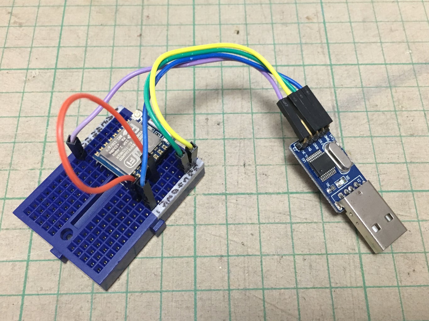
It is recommended program ESP8266 before soldering it with other components.
Download the source code here:
https://github.com/moononournation/ESP8266WiFiAnal...
Compile and program the ESP8266 with Arduino software.
You may find more details in my previous instructables:
Step 4: Sweet Box Patch


- Patch the box to fit in the LCD
- drill pair of holes for hanging key ring
Step 5: Battery Concern


In my previous instructables, I have measured the power consumption in different boards and battery connection. The ESP-12 with HT7333-A can make a good power saving circuit. I can skip a power switch for simpler design, the analyzer scan five times and fall into deep sleep mode. Simply press the reset can turn it on again. Assume scan 1 time consume 1.1 mAh, every day scan 5 times and deep sleep 1 hour consume 0.31 mAh, a 400 mAh can last a month:
400 mAh / (5 x 1.1 mAh + 24 x 0.31 mAh) ~= 31 days
Step 6: Soldering Work


Double check your LCD data for the pin definitions.
Here are the connection summary:
charge board B+            -> LiPo +ve
charge board B-            -> LiPo -ve
charge board out+          -> 3V3 regulator power input
charge board out-          -> 3V3 regulator GND, ESP GND, LCD GND, capacitors
3V3 regulator power output -> ESP Vcc, PNP transistor Emitter, capacitors
PNP transistor Base        -> 10 k resistor -> ESP GPIO 4
PNP transistor Collector   -> LCD Vcc, LCD LED

LCD SCK  -> ESP GPIO 14
LCD MISO -> ESP GPIO 12
LCD MOSI -> ESP GPIO 13
LCD D/C  -> ESP GPIO 5
LCD CS   -> ESP GPIO 15

ESP EN      -> 10 k resistor -> ESP Vcc
ESP GPIO 15 -> 10 k resistor -> ESP GND
ESP RST     -> reset button  -> ESP GND
Attachments

Step 7: Squeeze All in Sweet Box


Step 8: Attach the Key Ring

Step 9: Happy Scanning!

It's time to show off your work with friends!
Step 10: Stress Test


A baby very interesting in this object, so I have invited her help to make a stress test.
She will randomly perform:
- squeeze the box and turn on the scanning routine
- shake test
- drop test
- step test
- water resistant test
After few weeks test, I have summary the test result:
- A 500 mAh battery can operate over 3 weeks
- My soldering work can resist baby shaking and dropping shock
- The Tic Tac box can resist 70 cm height drop and 10 kg step on load
- The box also can resist a small amount of water
I will update the actual battery life later on ;>

First Prize in the
Invention Challenge 2017


