

Introduction: Build Your Own DMX Fixture - Arduino


Welcome to my second Instructables page. I have learned a lot from this site and this seems a great place to show my projects. I hope you find this project entertaining and helpful.
I'm eager to know what you think. Let me know in the comments, please keep in mind I'm a beginner and not a native speaker. All of your comments are welcome ;)
The Project
In this Instructable I will show you how to create a DMX fixture all on your own. With the right parts it surprisingly simple to make, you only need a couple of components. I will show you how to adapt the incoming DMX signal (+2.5V and -2.5V) to a suitable signal (5V) for your Arduino and how to process this signal. Further I will show you how to control high power LEDs via a PWM pin.
Watch the video for more information and see the DMX light in action.
Step 1: Project Overview and Background


My friends and I are no strangers to the Dutch party scene and sometimes we like to organise a parties ourselves. Only when we organise a party we don't have much lighting and therefore I made a few DMX fixtures myself. In the third picture you can see my first (successful) attempt to create a DMX fixture on my own.
Because my clumsy friend dropped this prototype I had to make a new one and I thought it would be a neat idea to post my progress on Instructables this time. Enjoy! I hope it can be useful for your project.
Step 2: Get Your Supplies

It's time to get your supplies! The most items on the list I got from eBay or Amazon. These items are widely available so I recon it won't be a problem to find them.
Parts
- High Power UV LEDs (700mA) incl. star plates
- ATmega328 IC
- 5V voltage regulator IC (L7805CV)
- N-channel mosfet (BUZZ11)
- Small transistor (2N2222)
- 10-dip Switch
- Signal converter IC (SN75176BP) or MAX485
- 16mhz cristal
- 22 pF ceramic capacitors [2x]
- 1 uF ceramic capacitor
- 10 uF electrolytic capacitor
- High power resistor (0.81ohm, 5W)
- 100K ohm resistor
- 10K ohm resistor [11x]
- XLR sockets (male and female)
- Power supply / adapter (32V and 16V, I salvaged this from an old printer)
- Heat sink
- Headers and pins
- Proto-board
- Material for the casing (I used compressed wood (in dutch: MDF))
Step 3: Time to Solder


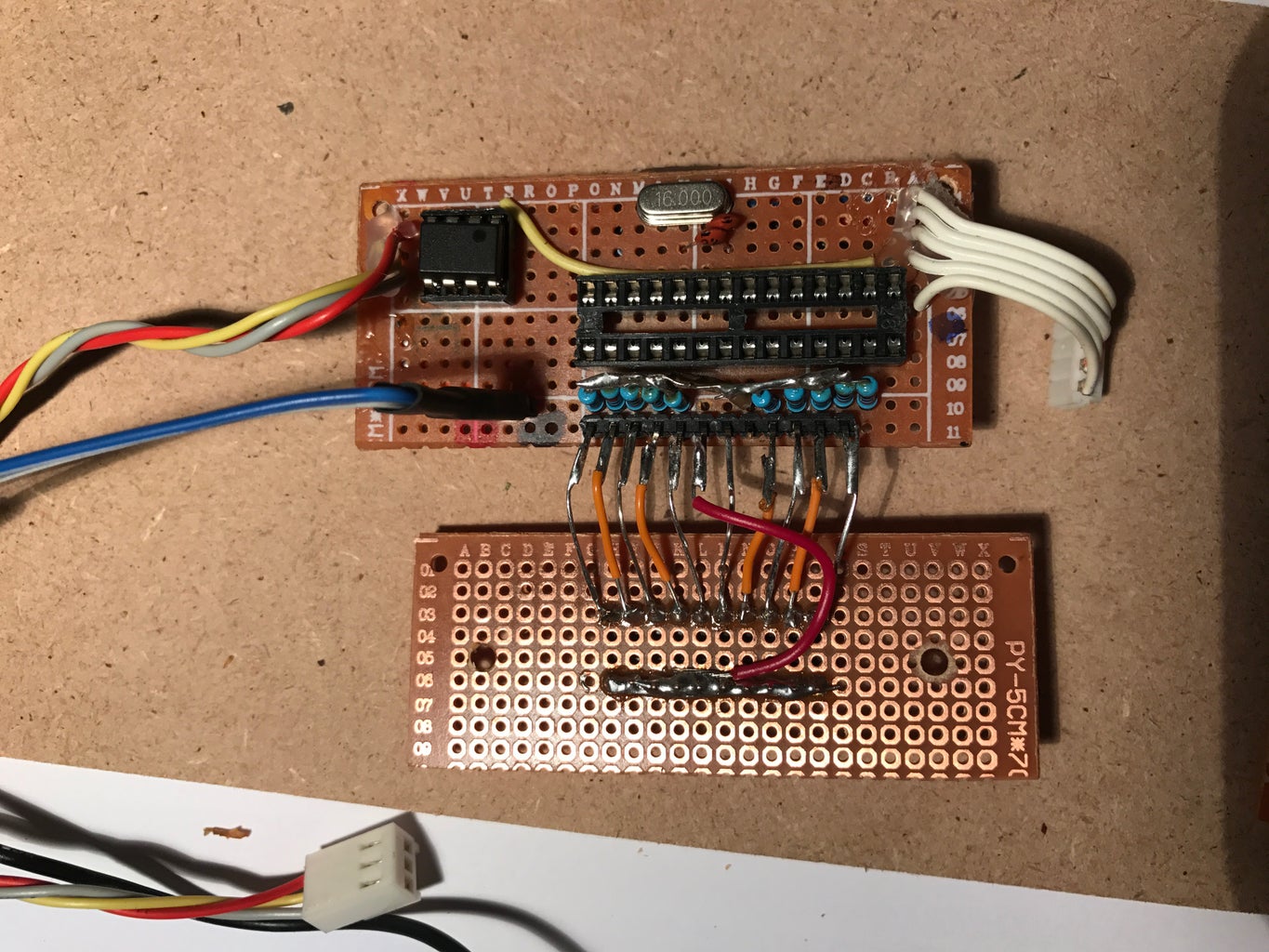
It's time to warm up the soldering iron and show off your solder skills.
Because the proto-boards where very small, I used three of them. I divided it in the power regulating board, control board and dip-switch board. I placed the dip-switch board upside down so the dip-switch is faced outside so the user can access it and change the DMX start address.
Step 4: Build the Case


This is always a problem for me. I don't have heavy machinery or a 3D printer at my disposal so I settled for compressed wood (MDF). Wood is easy to modify and I have a great control over the finished product.
For the most part I used screws and wood glue. The only part I didn't use wood glue is the front part, so I can access the inside.
I am aware that heat and wood are not best friends. My first attend was to use lenses for the LEDs, but I ditched them in the hope that the airflow will be sufficient to cool down the high power LEDs. Further the UV LEDs will function as a blacklight and will be a limited time on during the party. I expect to use this light only 10% of the time during the party and I hope the pauses between usages will be enough to cool down the LEDs.
I tested this and my theory was right, the inside of the casing never got hotter than 40 degrees celsius. Besides, because I used wood I can always implement a small fan later to increase the airflow and therefor cool down the LEDs faster.
Step 5: Schematics

Drive circuit High Power LEDs
I got this idea from Dan Goldwater. Check out his Instructable for more information and more variations of this driver circuit: https://www.instructables.com/id/Power-LED-s---si...
I intended to use a 0.75 ohm resistor but at the time I only had a 0.81 resistors laying around. This is not a problem because in this setup a higher impedance will result in a lower constant current and will therefor extend the life of the UV LEDs.
Dip-switch
I used pull-down resistors to stabilise the signals. It would be hard to control the light via DMX if the DMX start address changes during the party. I will lose the ability to control the light and it will make the light useless.
DMX signal conversion
To convert the incoming DMX signal (+2.5V and -2.5V) I used a signal convertor IC. I used the (cheap) SN75176BP for this. The more common IC is a MAX485. Connect the pins of the XLR socket like this:
XLR1 [GND] --> Ground / pin5
XLR2 [D-] --> B / pin6
XLR3 [D+] --> A / pin7
Don't forget to connect RO/pin1 and RE/pin2 to ground and DE/pin3 to VCC! Connect DI/pin4 to your microcontroller.
Note: this only works for incoming DMX signals. If you want to send DMX signals you need a different configuration. Maybe I will make a separate tutorial about this, let me know if this would be helpful.
Status LED
I forgot to draw in a 100K resistor between pin3 and the LED. I used a 100K ohm resistor because it still lets me see if the LED is blinking or not but the LED will not shine to bright so it will not illuminate the room.
Step 6: The Code
I did my best to describe the code as well as I could but I think there is room for some improvements, I'm open for suggestions. If you have any tricks on how to decrease the lines of code, let me know!
Before you aks me questions about the code, please watch the video. Here I explain almost every line of the code and its function.
Attachments

Step 7: Put It All Together


Now put it all together. Paint the case. Add some brackets to make it possible to hang the light from a truss and enjoy your light!
Fan
Just to be sure the fixture will not overheat I implemented a small fan I had laying around. I connected this to the 16V output of the power adapter and will run when the light receives power. So even when the LEDs are off, the fan can cool down the LEDs.
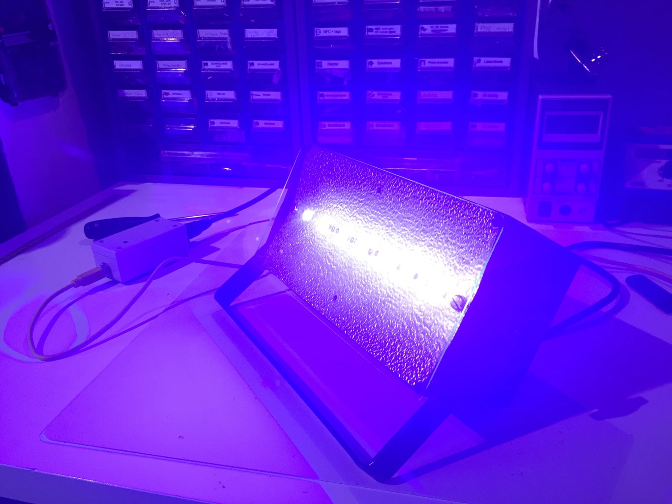
Blacklight effect
For the best effect I would recommend some things that will illuminate when the UV LEDs are on. The best is to use white or some fluorescence material (f.i. a highlight marker). For the first party I used some cut-outs of cardboard and sprayed them with a fluorescent paint. In the first picture the LEDs are turned off, in the second they are turned on. You can clearly see a difference especially in real life. I got some quite neat reactions from the crowd when the lights turned on.


