

Introduction: Arduino CNC Plotter (DRAWING MACHINE)


Hey guys! I Hope you already enjoyed my previous instructable "How to make your own Arduino training platform" and you are ready for a new one, as usual I made this tutorial to guide you step by step while making this kind of super amazing low cost electronic projects which is the "CNC plotter machine" known also as "CNC drawing" or just "Arduino CNC machine". ^_^
I found lots of tutorial accross the web that explains how to make a CNC Plotter, but with the lack of information it was a bit difficult to make such machine, thats the reason why I've decided to start this instructable where I will show you in details how to easily make your own drawing machine.
This project is so handy to make specially after getting the customized PCB that we’ve ordered from JLCPCB
to improve the appearance of our machine and also there is enough documents and codes in this guide to allow you create your machine easily. We've made this project in just 5 days only, just three days to get all the needed parts and finish the hardware making and the assemble, then 2 days to prepare the code and start some adjustments. Before starting let’s see first
What you will learn from this instructable:
- Making the right hardware selection for your project depending on its functionalities
- Prepare the circuit diagram to connect all the choosen components
- Assemble all the project parts (mechanical and electronic assembly)
- Scaling of the machine balance
- Start manipulating the system
Step 1: What Is a Plotter Machine


Since I've made this instructable for beginners, I should explain in details first what is the drawing machine and how it works!
As it is defined in wikipedia, CNC stands for Computer numerical control, a machine which is a computer-controlled structure that receives instructions through a serial port sent from a computer and moves its actuators depending on the received instructions. Most of these machines are stepper motor based machines which includes stepper motors in theme axis.
Another word to mentioned "axis", yes, each CNC machine has a defined number of axis that will be controlled by the computer program.
In our case the CNC plotter that we made is a double axis machine "details in picture 1" that has a small stepper motors in its axis "stepper in picture 2" these steppers will move an active tray and make it move in a double axis plan to create the drawing design using a drawing pen. The pen will be holded and released using a third engine in our structure which will be a servo motor.
Step 2: Stepper Motor Is the Main Actuator


A stepper motor or step motor or stepping motor is a brushless DC electric motor that divides a full rotation into a number of equal steps. The motor's position can then be commanded to move and hold at one of these steps without any position sensor for feedback(an open-loop controller), as long as the motor is carefully sized to the application in respect to torque and speed.
First verse, from where to get the stepper motors for our project, well easy, just grab an old DVD reader like the one in picture 1 above, I’ve got two for 2 dollars, than all what you need to do is disassemble it to extract the stepper motor and its support, as it shows picture 3, we will need two of them.
Once you get your motors from the DVD reader, you should make them ready to use by identifing the motor coils ends. Each stepper motor has two coils and using a multimeter you can identify the coil ends by measuring the resistance between the motor pins connector "as show picture 5" and for each coil it should be about 10Ohm measured. After identifing the motor coils just solder some wires to control the motor through them "see picture 6"
Step 3: The Circuit Diagram


The heart of our machine is an arduino Nano Dev board that will control the movement of each actuator depending on the instruction received from the computer, in order to control these stepper motors we need a stepper motor driver to control the speed and direction of each actuator.
In our case we will use an L293D H bridge motor driver "see picture 3" which will receive the motor command sent from arduino through its inputs and control the stepper motors using its outputs.
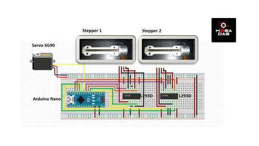
in order to connect all the needed parts together with our Arduino board I've made the circuit diagram that shows picture 1 where you should follow the same connection for both stepper motors and the servo motor.
The picture 2 explain in details through a schematic the circuit diagram and how it should be the links between the Arduino and the other components, for sure you can adjust these links depending on your needs.
Step 4: The PCB Making (Produced by JLCPCB)


About JLCPCB
JLCPCB (Shenzhen JIALICHUANG Electronic Technology Development Co., Ltd.), is the largest PCB prototype enterprise in China and a high-tech manufacturer specializing in quick PCB prototype and small-batch PCB production. With over 10 years of experience in PCB manufacturing, JLCPCB has more than 200,000 customers at home and abroad, with over 8,000 online orders of PCB prototyping and small quantity PCB production per day. The annual production capacity is 200,000 sq.m. for various of 1-layer, 2-layer or multi-layer PCBs. JLC is a professional PCB manufacturer featured of large scale, well equipment, strict management and superior quality.
Talking electronics
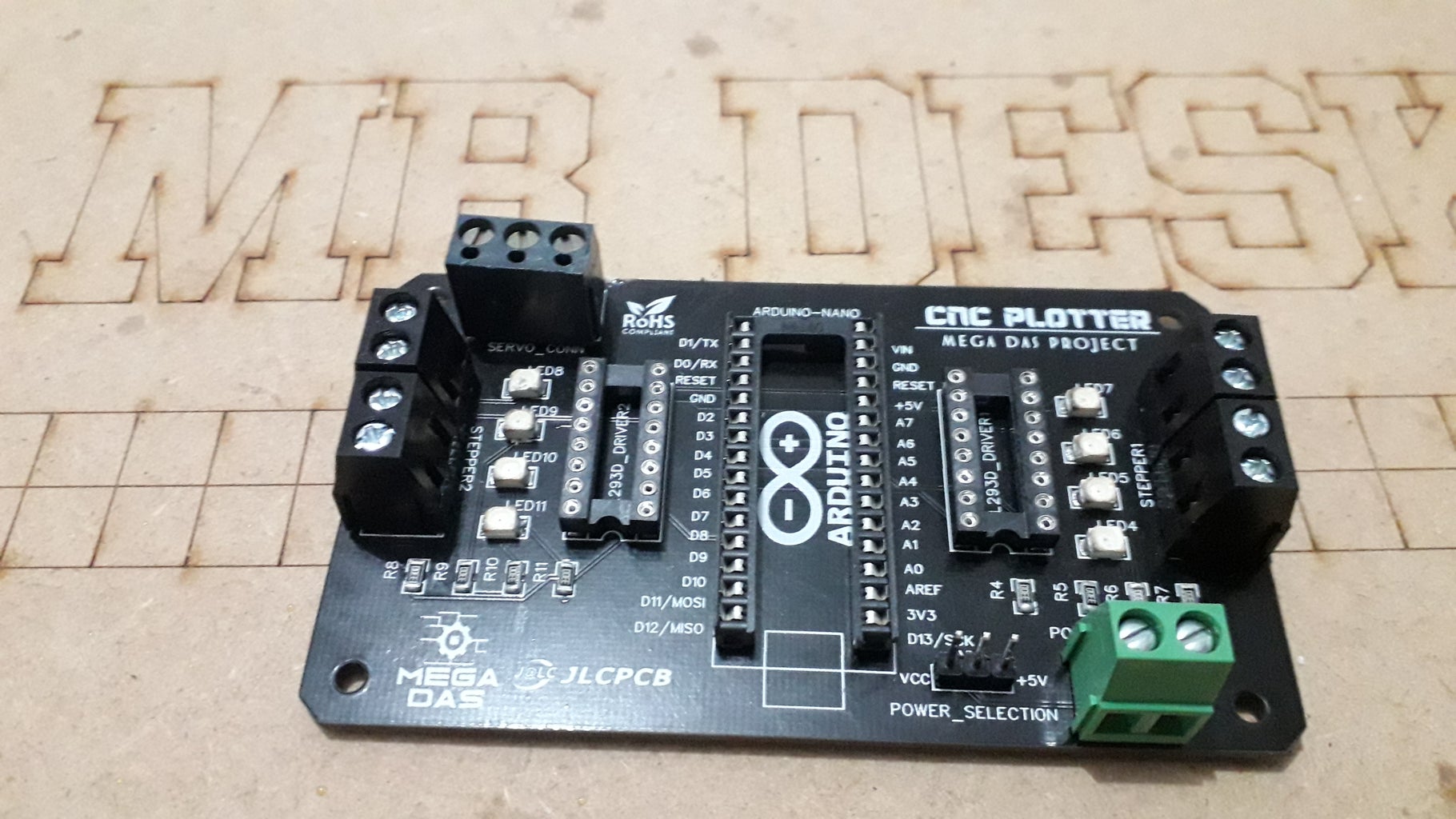
After making the circuit diagram I transformed it into a PCB design to produce it "see picture 5,6,7,8", in order to produce the PCB, I have chosed JLCPCB the best PCB suppliers and the cheapest PCB providers to order my circuit. with them reliable platform all what I need to do is some simple clicks to upload the gerber file and set some parameters like the PCB thickness color and quantity, then I’ve paid just 2 Dollars to get my PCB after five days only. As it shows "the picture 1,2,3,4" of the related schemtic.
Related download files
You can get the Circuit (PDF) file from here. As you can see in the pictures above the PCB is very well manufactured and I’ve got the same PCB design that we’ve made for our main board and all the labels and logos are there to guide me during the soldering steps. You can also download the Gerber file for this circuit from here in the case you want to place an order for the same circuit design.


Step 5: Design a Support for Your Machine!


In order to bring a better appearance for our machine I decided to designe these three parts "see picture 1" using Solidworks software, these parts will help us to assemble the DVD readers together, I’ve got the DXF files of these parts and with the help of my friends in FabLab Tunisia I’ve got the designed parts produces using a CNC laser cutting machine, we used a 5mm MDF wood material to get these parts produced. Yet another designe which is the drawing pen holder, I've got it through a 3D printing process. And you can download all the related files from the links down below.
Attachments
Step 6: Ingredients

Now let’s review the necessary components that we need for this project, I'm using an Arduino Nano as mentioned above, it will be the heart of our machine. The project also include two stepper motors with them drivers ICs and a servo motor. You will find bellow some recommended amazon links for the appropriate items
In order to create this kind of projects we will need :
- The PCB that we’ve ordered from JLCPCB
- An Arduino nano : https://amzn.to/2SDSTgO
- 2 x L293D H bridge driver : https://amzn.to/2C6PWyb
- 2 x IC sockets DIP 16 pin : https://amzn.to/2RAyCvu
- 1 x IC socket DIP : https://amzn.to/2SPXMTW
- SIL and Screw header connectors : https://amzn.to/2Ril1JC
- 1 x servo motor SG90 : https://amzn.to/2VEsAZF
- 2 x DVD readers :
- The 3D printed parts
- The laser cutted parts
- Some screw for the assembly
- The pen that we've got as gift from JLCPCB or any other drawing pen
Step 7: Electronic Assembly and Test


We move now to the soldering assembly of all the electronic components. As usual you will find on the top silk layer a label of each component indicating its placement on the board and this way you will be 100% sure that you will not make any soldering mistakes.
Make some tests
After soldering the electronic components "see picture 1", I screw the DVD reader to the X axis plate and I did the same for the main board than I placed the motor wires in them screw header to make a simple test using a stepper motor test code "see picture 2". As you see the stepper moves fine and we are on the right path.
/************************************************************************************************************************************************************************
* - Author : BELKHIR Mohamed * * - Profession : (Electrical Ingineer) MEGA DAS owner * * - Main purpose : Industrial Application * * - Copyright (c) holder : All rights reserved * * - License : BSD 2-Clause License * * - Date : 20/04/2017 * * ***********************************************************************************************************************************************************************/ /*********************************** NOTE **************************************/ // Redistribution and use in source and binary forms, with or without // modification, are permitted provided that the following conditions are met:// * Redistributions of source code must retain the above copyright notice, this // list of conditions and the following disclaimer.
// * Redistributions in binary form must reproduce the above copyright notice, // this list of conditions and the following disclaimer in the documentation // and/or other materials provided with the distribution.
// THIS SOFTWARE IS PROVIDED BY THE COPYRIGHT HOLDERS AND CONTRIBUTORS "AS IS" // AND ANY EXPRESS OR IMPLIED WARRANTIES, INCLUDING, BUT NOT LIMITED TO, THE // IMPLIED WARRANTIES OF MERCHANTABILITY AND FITNESS FOR A PARTICULAR PURPOSE ARE DISCLAIMED
/*
─▄▀▀▀▀▀▀▀▀▀▀▀▀▀▀▀▀▀▀▄ █░░░█░░░░░░░░░░▄▄░██░█ █░▀▀█▀▀░▄▀░▄▀░░▀▀░▄▄░█ █░░░▀░░░▄▄▄▄▄░░██░▀▀░█ ─▀▄▄▄▄▄▀─────▀▄▄▄▄▄▄▀
*/ #include // Include the stepper Motor librarie const int stepPerRotation = 20; // Number of steps by turn. Standard value for CD/DVD // Indicate X axis stepper motor Pins Stepper myStepperX(stepPerRotation, 8,9,10,11); void setup() { myStepperX.setSpeed(100); // Stepper motor speed myStepperX.step(100); delay(1000); myStepperX.step(-100); delay(1000); } void loop() {}
Step 8: Assembly of the Mechanical Parts


We continue the assembly of our structure by screwing the second stepper motor to the Y axis plat "see picture 1". Once preparing the Y axis you will have both axis ready to create the double axis plan that we spoke about it in the first step "see picture 2". all what you need to do is placing the two axis in a 90° "see picture 3".
Making of the pen holder
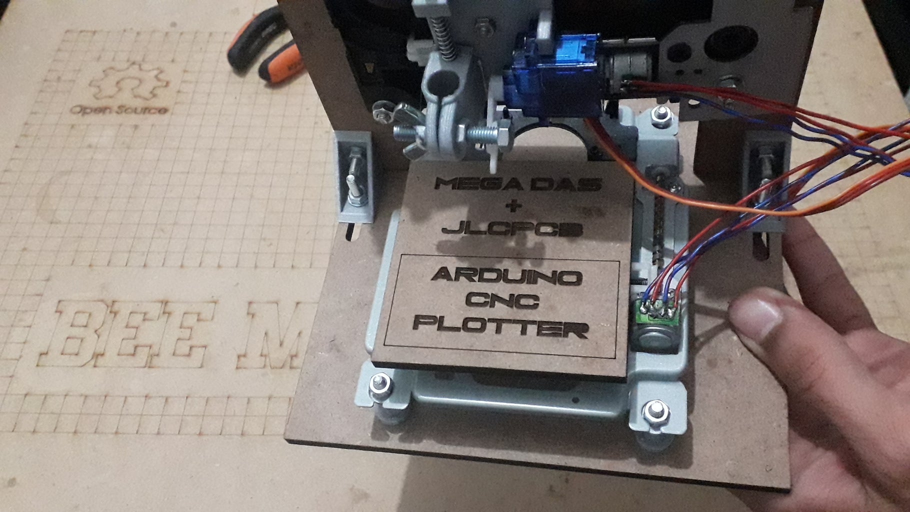
We prepare the pen holder by placing a small axe into a spring to hold the 3D printed pen holder and then we screw the servo motor to its placement "see picture 4", the pen holder is ready so we stick it to the carriage of the Y axis using some hot glue or any other means to make it able to slide on the Y axis following the stepper motor steps "see picture 5", then we stick our active plat to the carriage of the X axis "see picture 6", and we finish with the screwing of the engines wires to them connectors on the board. After some arrangement, we have our mechanical design ready for the action 'see picture 7'.
Step 9: Software Part


Moving to the software part, we will combine three softwares in order to turn the machine alive, I've made a short description in the first picture, we will make our design using Inkscape software that produces a gcode file needed for our machine and for sure in order to understand the gcode instructions the machine should have its own code that we will be uploaded using Arduino IDE software, the last part is how to link the machine’s code to the gcode file, this is performed by processing software.
The first step is uploading the arduino board scketch that you can download from the link down below and do not forget to update the stepper motors pin according to your shcematic.
Note : if you are using the same schematic as ours so the code will be working fine and no need to change anything in it.
Preparing the Gcode 'Inkscape'
Then we move to Inkscape and we adjust some parameters 'see picture 1' like the paper frames and units 'see picture 2' , we prepare our design and save it on MakerBat unicon format 'see picture 5,6', if this format is not available on your Inkscape version, you can place an add-on to have it, once you click on (save) a new window will appear for Gcode file parameters adjustments, all what you need to do is following the same adjustment as ours and everything will be fine just follow 'picture 7,8,9' then you set these parameters this way, and you have your gCode file.
Note : you can't save the Gcode file under the required format if you are using an Inkscape version higher than version 0.48.5
Linking the machine to the Gcode file 'Processing 3'
Moving to processing software, it is a bit like the Arduino IDE 'see picture 10' so you should open the 'CNC program' file That you can download from the link down below and just run it 'see picture 11', a second window will appear, you need to press the latter p in you keyboard to select the COM port of the machine 'see picture 12', and press the latter g to select the desired gcode file, once you select it the machine will directly start drawing.
Attachments
Step 10: Test and Results


And here we are the time is here for some test, once uploaded the Gcode file the machine start drawing and I really liked the LED flickering that shows the sequences sent to each stepper motor.
The designs are very well done, and you can see guys the project is amazing and easy to make as well,
Don’t forget to watch our previous project which is “how to make your own arduino training platform". And subscribe to our YouTube channel for more awesome videos.
One last thing, make sure that you are doing electronics everyday
It was BEE MB from MEGA DAS see you next time

Participated in the
PCB Contest


