

Introduction: Card Sorter for a Trading Card Machine (Update 2019-01-10)


Card Sorter for a Trading Card Machine
The Change Log can be found in the last step.
The Background
I already explained the motivation of my project in the Card Feeder article. But in short, my children and I have amassed a large amount of Trading Cards by now. The handling, sorting, etc. is very difficult with these quantities. We have already tried it, but we gave up frustrated. For this reason I want to build a Trading Card Machine, which should take on different tasks.
Trading Cards should automatically be
- managed (Which cards do I have?, Which ones are missing?)
- sorted (Block, Language, Set, Series, etc)
- rated (How valuable are my cards?, How much money do I have to spend for a full set?)
- traded (Buy and Sell)
Because of this ambitious goals, I decided to split the huge machine into 3 parts.
- Card Feeder - a machine which grab and transport a single card out of a card stack
- Card Scanner - a part where the cards will be analyzed
- Card Sorter - a machine which will store the identified cards
This Instructable is about the 3rd part, the Card Sorter. Cards that have passed through the machine will be stored in the Card Sorter. The decision on what is sorted is made by the Card Scanner. The Card Sorter is only responsible for the right place to store the cards.
The focus of the Trading Card Machine is currently on the World of Warcraft Trading Cards, as we have by far the most cards from this type. That's why I designed the Card Sorter so that every set has its own storage compartment. There were 21 sets in the WoW universe, so I need space for 21 + 1 storage opportunities. The additional tray is for cards that were not recognized by the Card Scanner or that could not be assigned to the Card Sorter.
There are many ways to do it.
It was important to me:
- as few mechanical and electrical parts as possible
- to use gravity
- cool look
- a lot of movement
- visible movement
It was NOT important to me:
- space saving, lightweight, portable
- effective or fast
After many considerations and a few sleepless nights, I had decided on the following variant:
The Card Feeder is in the middle at the highest position and put the cards on a ramp. These then slide down into the Card Scanner. After the Scanner, the cards slide down over a ramp into one of the 22 compartments. These 22 storage areas are arranged in a circle around the center and can be positioned by a motor to the ramp accordingly.
Exactly this part I want to show you.
Let's do it!
In this instructable I will show you Part 3 - How to create the Card Sorter.
Step 1: Tools and Materials


Tools and Materials
Here's what I used to create the Card Sorter:
Tools:
- Cutting mat
- Rulers
- Cutter
- Compass with pencil and blade
- Solvent-containing adhesives (UHU HART and tesa)
- Tape
- Drill + 5mm wood drill bit
- Hot glue gun + glue gun sticks
- Router
- Milling compass
- 8mm spiral cutter bit, 12mm core box cutter bit
- Sanding paper
- Rubber bands
- Screwdrivers
- Pencil, markers
- Scraper or something similar with rounded corners
- Center punch
- Drill Station (not on the picture)
- 3D Printer (not on the picture)
Materials:
- 3mm cardboard (I used it for the Boxes and the Timing Belt)
- 9mm birch plywood (main material for the Card Sorter)
- 12mm steel balls
- DIN A3 paper
- PLA filament (not on the picture)
- Wood glue
- Adafruit Stepper Motor
- Arduino UNO
- Adafruit Motor Shield power supply
- Adafruit Motor Shield V2
- Adafruit Motor Shield V2 Library
- Some kind of computer, equipment, cables, etc. to connect and program the Arduino UNO (not on the picture)
Step 2: Prototype


Prototype
As mentioned in the Intro, 22 Boxes should orbit around the Card Feeder which is placed in the center, but how to do that? After some researches I found what I was looking for. The Thrust Ball Bearing was the key to success. Since this was the challenge in this project, I created a Prototype of it.
I made the 1st version out of cardboard and put them together using craft glue and hot glue. It consisted of a base area, two different large outer rings and one smaller circle in the center. The distances between the outer rings and the inner circle were chosen so that 12mm steel balls can run along the groove. 12mm, why 12mm balls? For one thing, I had a lot of it in stock, on the other 12mm are a common size for tools. There are 12mm drills, 12mm cutter bits, etc. In principle, it worked well. Unfortunately, good is not good enough. Cardboard is simply too soft and creates a lot of friction, making the Thrust Bearing hard to move. Everything is possible, but the effort was too high for me in this case.
That's why I switched to MDF in the 2nd Prototype. With my router I first milled the outer radius and then a 30mm wide groove into the piece of wood. The groove is for a ball cage. Afterwards I used a 12mm core box cutter bit to mill the groove for the steel balls. Last but not least, I cut out the inside radius. I have repeated the whole process twice and thus received a top and bottom for the Thrust Bearing.
I created a ball cage out of 3mm MDF. I used a compass to distribute 6x 12mm holes evenly on the cage. Then I drilled them on the drill press.
To reduce friction, I have sealed and sanded the contact surfaces.
Then it was time for some tests.
Test 1 => 6 steel balls with the ball cage
Test 2 => 6 steel balls without the ball cage
I was very satisfied with both variants. Test 1 was more consistent due to the even distribution of the balls through the cage. Test 2 was smoother without the additional friction of the ball cage.
I also thought about a mechanism to hold the Thrust Bearing together, but then I did not pursue it. Maybe a topic for the future.
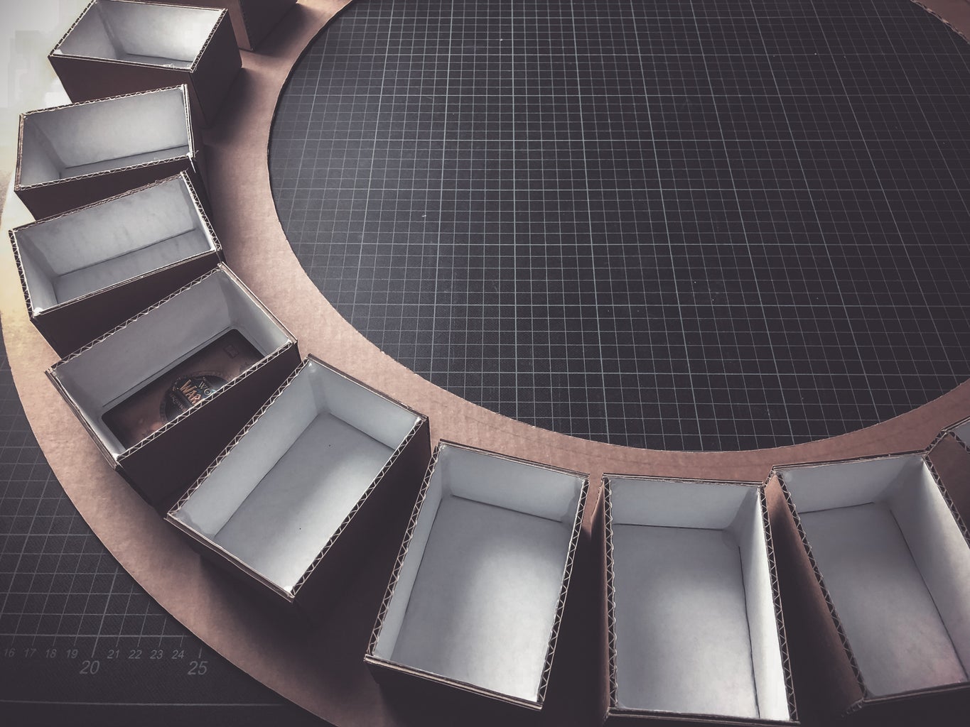
In order to get a feel for the sizes, I transferred the space that the 22 Boxes need to a piece of 3mm cardboard. With a compass and a cutting blade I cut out the shape (450mm outer radius and 300mm inner radius). The measurements fitted very well and left enough room for any changes.
Step 3: Design


Design
(You can find the drawing as a pdf in the attachment!)
I transferred the ideas and insights from the Prototype to Fusion360 and created a more accurate model there.
I started with the bottom of the Thrust Bearing. A circular ring with 450mm outer and 300mm inner radius formed the base. I have extruded this 2D sketch to 9mm (thickness of the wood that I will use).
In the next step I created a groove for the 12mm steel balls. The groove is only 2mm deep.
To get the top of the Thrust Bearing, I copied the whole object and flipped it horizontally.
Between bottom and top, I've created 6x 12mm balls and evenly distributed them into the groove.
With the help of a 2nd sketch I created a Timing Belt on the inside surface of the upper side. In previous projects I already had good experiences with timing belts. That is the main reason to use it in this project again. The Timing Belt is mounted directly on the Thrust Bearing and can be driven by a Drive Wheel attached to a Motor.
On top of the upper side are the 22 Boxes for the cards.
Step 4: Boxes


Boxes
(You can find the box template as a pdf in the attachment!)
The Boxes are used to store the cards. Temporarily I made them out of cardboard. The size of a box is determined by the card itself. Most cards have a size of 63 x 88mm. So that the cards have enough space, I added 3mm to each side.
- Inside 69 x 94mm.
- Outside 75 x 100mm (I used a 3mm cardboard)
- Height 50mm (That's enough for about 100 cards)
For the shape of the box I used an online generator. I printed the box pattern on A3. After rough cutting the template with the cutter, I glued it to a piece of 3mm cardboard with tesa liquid glue. This time I did not take care on the backside. Normally it is important and necessary to apply glue and paper on both sides, as otherwise the cardboard will bend during the drying phase.
Then I cut out the shape with a cutter and a ruler on my cutting mat. I worked my way through the material in several steps. Not the whole at once!
Since I did not want to fold the sides of the box, as it was actually specified in the template, I cut off all folding surfaces. With a blunt object, in my case a spatula with rounded corners, I have traced all the folding edges in several passes. That made it easier to fold. Then I folded it to a box and temporary fixed all sides with a tape. Finally I glued everything together with a hot glue gun. After the drying time was over, I removed the tape.
I repeated this process 22 times.
Step 5: Wooden Thrust Bearing


Wooden Thrust Bearing
The perfect part for my project is a Thrust Bearing. The bottom of the bearing will be fixed and only the top is movable. Basis were two 1000 x 1000 x 9mm birch plywood plates.
I started with the bottom of the Thrust Bearing. As a guide, I have drawn all measurements with a compass to the wood.
- Outer radius 450mm
- Groove for the ball, radius 375mm
- Inner radius 300mm
I created the pivot point for the milling compass with a drill and a 5mm wood drill bit. Then I started with the outer radius (450mm), for this I have used a router, a milling compass and an 8mm spiral cutter bit. In order not to damage the table, I put the plywood a bit higher on some leftover wood. In 3mm steps, I worked through the wooden plate.
Afterwards I switched to a 12mm core box cutter bit and milled a groove for the 12mm steel balls with a radius of 375mm and a depth of 2mm.
Then I changed back to the 8mm spiral cutter bit and cut out the inner radius of 300mm.
After a short test that the steel balls were running smoothly, I have created the top of the Thrust Bearing on the same principle and with the same materials.
Finally, I sanded the surfaces, corners and grooves of the bearing.
I evenly distributed 12mm steel balls in the groove on the bottom and then I put the top on.
It took a certain amount of power to set the bearing in motion. But after that it works surprisingly well.
For the moment I did not use a ball cage, because I did not have a really good idea how to implement it. A variant as in the Prototype would have been possible, but this would have to be specially built so that the cage rests only on the balls and not on the bottom and top.
Do you have a good idea?
Step 6: Cardboard Timing Belt


Cardboard Timing Belt
The top of the Thrust Bearing will be driven by a motor. The power from the Motor is transmitted to a Timing Belt via a Drive Wheel. The belt is firmly connected to the bearing which leads to a rotational movement. To implement this, I created a Timing Belt made out of cardboard.
I cut out 3x 9mm wide strips from a piece of 3mm thick cardboard. I used again a cutter, a ruler and a cutting mat. Then I made cuts in the top layers of the cardboard. I repeated this process for all 3 cardboard strips. What was left after peeling of all the little top layer pieces was my Cardboard Timing Belt.
To reach the right length, I glued all three strips together using some tesa liquid glue.
Then I glued the Timing Belt with some hot glue to the inner radius of the Thrust Bearing upper side. The bearing and the belt are both 9mm wide, so the adjustment was very easy. I used a center punch to press the belt (each tooth) to the bearing. It is important, that there is no gap between Timing Belt and Thrust Bearing. Otherwise, it will cause uneven rotation. Excess hot glue can easily be wiped off the surface.
The result looked really nice and worked even well. However, it is still cardboard. The teeth are not the strongest. For that reason I decided to do a little stabilization. In contrast to the Card Feeder I used only wood glue to fill the holes in the Timing Belt. In retrospect, don't do that. :) It was so intense and timing consuming. I had to fill every tooth with glue 8 times. If you want to stabilize cardboard, please look at this step in the Card Feeder.
Nevertheless, the teeth are hardened and very solid.
Step 7: 3D Printed Drive Wheel


3D Printed Drive Wheel
(You can find the wheel as a stl in the attachment!)
The top of the Thrust Bearing will be driven by a stepper motor. For that I need a Drive Wheel which fits on the motor shaft and also to the Cardboard Timing Belt. Because of this special requirement I designed and printed the Drive Wheel.
I created a wheel for my motor, which has a 5mm shaft, in Fusion360. The decisive reason for the diameter of the wheel is the position of the teeth on the Timing Belt. It is important to work only with full teeth. Otherwise, the wheel would not fit perfectly into the timing belt. This will cause to an uneven rotation and lost steps inside the motor. In my case this means that the Drive Wheel has to be 63mm in diameter.
With that said, I created 2D Sketch with a 63mm circle and extruded it to 9mm (thickness of the bearing and the belt).
I also added an attachment to mount the wheel to the motor shaft. This attachment is a kind of pocket in which a M3 hexnut will fit. A M3 screw can be screwed in perpendicular to the shaft. With that little system it can be mounted to the motor.
I exported the object as STL-file and imported it into the Cura WANHAO Edition. After I made some basic adjustments (Rotation, Infill %), I create the g-code and sent it to my 3D Printer.
After the process was finished, I clamped the Drive Wheel into my Drill Station. With medium speed and some sanding paper I roughen the surface to enhance the gluing properties. In the next step I put some glue (UHU HART) on a piece of Cardboard Timing Belt and glued it onto the Drive Wheel. I used some rubber bands to hold everything in place.
I used the same method to stabilize the Timing Belt on the drive wheel as I did it on the Thrust Bearing and filled all holes in the belt with wood glue.
Step 8: Electrical Parts


Electrical Parts
As already mentioned, the top of the Thrust Bearing is driven by a motor. For my point of view the best motor for this task is a stepper motor.
I used the following motor, because I already had them. But I realized quickly that it was not the best motor for the job. It was to weak regarding speed and torque. But for the first test the motor is ok.
No, totally wrong. I realized nothing. I made a stupid mistake. It helps if you can read. :) I use a 12V/350mA Motor via USB??? No way. Of course the motor has no power. I bought a 12V/3A power supply and connected it to the Adafruit Motor Shield. The behaviace is totally different.
- Adafruit
- 200 steps per revolution, 1.8 degrees
- Bipolar stepper
- 12V rated voltage at 350mA max current
- 28 oz*in, 20 N*cm, 2 Kg*cm holding torque per phase
The stepper motor is connected to the Adafruit Motor Shield V2 via 4 wires. This shield is stacked on an Arduino Uno. The Arduino was powered by USB from a computer. The motor should supplied by a DC power supply, but for my short tests I used the USB power supply.
No, wrong decision.
One important part is the homing of the Card Sorter. There will be no position sensors for the Boxes. Everything will be realized with steps. So it is essential that on anytime the Card Sorter knows which step position he has and which step position the Boxes have. At the moment I did the homing with a simple switch on a breadboard connected to an input pin on the Arduino. In the end I have to create a mechanism on or inside the bearing. I think IR break beam sensors will be the best solution. Another future task.
Step 9: Coding


Coding
(You can find the Arduino code as a ino in the attachment!)
If you need some Arduino basics => Arduino Class
Let's say...
the Card Feeder will give us a card at the position of 9 o'clock. So the stepper motor should deliver us the right box to the right time at position 9 o'clock to store a card. To do so the stepper motor can rotate the top of the Thrust Bearing clockwise and counterclockwise.
box number 10 is now on position 9 o'clock. To bring the box to this position the stepper has to go 800 Steps. Now we switch of the Card Sorter completely. On the next restart we would have a problem because the system don't know the actual status. Is it right? Is it wrong? In our case it would be wrong, because the 800 steps from our last run are now the new 0. Everything is shifted. At the beginning of a routine, box 1 should be always on position 9 o'clock with 0 Steps.
Long story short,
- The stepper motor rotates the right box to the Card Feeder
- after every restart a homing is necessary.
The Card Sorter has 22 Boxes on top which are evenly distributed. That means 360°/22 ~ every 16° is a box. The stepper motor has a 1.8° step angle (200 steps/revolution).
I have done a quick test to identify the right steps to reach the 16°. I created two cardboard templates with all angles and positions and also marked a position on the Drive Wheel. Then the stepper motor turned one turn (200 steps). I marked this position on the template and measured it with a protractor.
200 steps => 40°, which means to reach the 16°, 80 steps are required. The numbers are rounded, so maybe there will be some adjustment in the final Trading Card Machine. In the video I'm using INTERLEAVE. So I have to double the steps.
Now let's have a look at the code.
It's based on the Adafruit AccelStepper example. I deleted the two not needed motors and add some own functions. But first I had to install Adafruit Motorshield v2 library and the AccelStepper library
<p>// Requires the Adafruit_Motorshield v2 library<br>// https://github.com/adafruit/Adafruit_Motor_Shield_V2_Library
// And AccelStepper with AFMotor support
// https://github.com/adafruit/AccelStepper</p><p>// This tutorial is for Adafruit Motorshield v2 only!
// Will not work with v1 shields</p><p>#include "wire.h"
#include "accelstepper.h"
#include "adafruit_motorshield.h"
</p><p>Adafruit_MotorShield AFMStop(0x60); 								//Default address, no jumpers</p><p>Adafruit_StepperMotor *myStepper = AFMStop.getStepper(200, 2);		//Connect a steppers with 200 steps per revolution (1.8 degree) to terminal 2</p><p>																	//Wrappers for the motor
void forwardstep() {
myStepper->onestep(FORWARD, DOUBLE);								//DOUBLE or INTERLEAVE or MICROSTEP!
}
void backwardstep() {
myStepper->onestep(BACKWARD, DOUBLE);								//DOUBLE or INTERLEAVE or MICROSTEP!
}</p><p>AccelStepper stpCardSorter(forwardstep, backwardstep);				//Wrap the stepper in an AccelStepper object

int intStpMoveTo = 0;												//Steps/Position for the motor
int pinHome = 11;													//Homing switch connected to PIN 11
bool bolHome = false;                                             	//Initialvalue = not in the right position => false</p><p>void setup()														//###SETUP###
{
Serial.begin(9600);													//Start the serial
Serial.println("Setup!");
AFMStop.begin(); 													//Start the top shield</p><p>stpCardSorter.setMaxSpeed(200.0);									//Set Speed
stpCardSorter.setAcceleration(100.0);								//Set Accereration
stpCardSorter.moveTo(2000);											//Steps/Position ~ 1760 Steps = 1 rotation of the bearing</p><p>pinMode(pinHome,INPUT);												//Homing switch = INPUT
bolHome = _homeCardSorter();										//Start the homing process

}</p><p>void loop()															//###LOOP###
{
  //Serial.println("Loop!");
  if ((Serial.available() > 0) && (bolHome == true))              	//Serial active and bearing on the 0-Position
  {				                                                    //YES
    int intVal = Serial.parseInt();									//Serial buffer => INT
    Serial.print("Move Stepper to position: ");                   	//Print serial
    Serial.println(intVal);
    stpCardSorter.moveTo(intVal);									//Move Card Sorter Stepper to position    </p><p>    if (stpCardSorter.distanceToGo() == 0)                        	//If Card Sorter Stepper reached the position
    {							                                    //YES
	    stpCardSorter.stop();										//Motor STOP
    }
  }
  stpCardSorter.run();                                            	//Motor RUN
}</p><p>bool _homeCardSorter()                                              			//###_homeCardSorter###
{
  Serial.println("Homing!");
  bool result;</p><p>  while ((digitalRead(pinHome)==LOW) && (stpCardSorter.distanceToGo() != 0))    //Motor RUN until => Found 0-Position or reached max. distance
  {
    stpCardSorter.run();
  }

	stpCardSorter.stop();                                                       //Motor STOP  </p><p>  if (digitalRead(pinHome)==HIGH)                                               //Found 0-Position
  {
	  stpCardSorter.setCurrentPosition(0);                                     	//Reset actual position to 0
    Serial.println("0-Position found");
	  return result = true;                                                   	//Return => 0-Position found => everything ok
  } else
  {
    Serial.println("0-Position NOT found!!");
	  return result = false;                                                   	//Return => 0-Position NOT found => error
  }
}</p>
Homing:
The Card Sorter has to be moved after every restart to the home position. I created a new function and included it in the setup routine. The motor turned a little more than one turn, which are 1840 steps, with slow speed. If the 0-position switch is found during this time, the motor stops and the step position is set to 0. If the switch is NOT found during this rotation, it will create an error message.
Serial Interface:
In the final Trading Card Machine the Card Scanner will send the required position to the Card Sorter. At the moment I use the Serial Monitor to talk with the Sorter. I can see some messages what the code is doing and I can send some positions (steps) to the motor. For example 80 Steps for the first box, 800 for the 10th box, etc.
Step 10: The End
The End
Card Sorter finished!
I've created a video in which I show you how I built it. You can also see the Sorter in action.
I hope you like it.
I really like the look and the size of the Card Sorter. I'm also quite happy with the function, but as I already said there are some open To-Do's:
- find a good way to create a ball cage
- create a clamping system to hold the bottom and top from the Thrust Bearing in place
- buy and implement a bigger motor => Done! Change Log V0.1
- implement an IR Break Beam homing switch
No question, I will work on them and find a solution. If there is anything to share, I will update this Instructable.
Similar to the Card Feeder, you can use the main idea (Driven Thrust Bearing) for many things. If you create something, I really would like to see your ideas and solutions.
I would appreciate any criticism, comments or improvements. Whether in relation to the Card Sorter, Photos, Skills, Writing or Language.
I will move on to the next part of the Trading Card Machine; The Card Scanner. In my next update I will show you how I (will) built it.
If you do not want to wait until the next update, you can see some news on Instagram.
Thank you for taking time to read about my project!
Have a great time.
Servus and cu next time!
Step 11: Attachment
Attachment
Here you can find additional files.
If you need anything else, feel free to ask!


Step 12: Change Log
Change Log
- V0.0 2019-01-02
- Project published
- V0.1 2019-01-10
- Step Intro - Add Change Log link
- Step 1 Tools and Materials - Add Adafruit Motor Shield V2 power supply
- Step 8 Electrical Parts - Update the Step with new knowledge
- Step 10 The End - Update To-Do's
- Step 12 - Change Log Create a new Step


