

Introduction: The Continuity Tester!


Hey Guys, I am back to instructables after a really long time. I'd been busy for a long while now, so let's get back to topic.The Name itself describes this project. ''The Continuity Tester !!''
Anyways, Recently I destroyed my Digital Multimeter while working with an AC project, so I needed an alternative to test my prototype circuits, so I thought this should do the job. Well, Enough of this intro, let's Build it!!
Step 1: Gather the Components!

For this project, the components I used, most of them I salvaged from older circuits. (Don't Worry I'll upload that one day)
OK, moving on, You'll need:
1) Piece of Perf Board or ProtoBoard( I had a piece laying around)
2)A 6-12V Piezo Buzzer (I think that's what its called or simply put 'A Buzzer')
3)2 Leds (I used one Green and another Red led)
4)2X100 ohm Resistors (I could have used 1k ohm resistors but it reduced the sound intensity of the Buzzer)
5)9V Battery and Battery Clip
Note:
You'll also need Soldering Iron and Wires but yeah those are the necessary things so no need to specify.
Caution:ALWAYS PERFORM SOLDERING IN A WELL VENTILATED ROOM. TAKE NECESSARY PRECAUTIONS.
Step 2: Testing the Circuit !

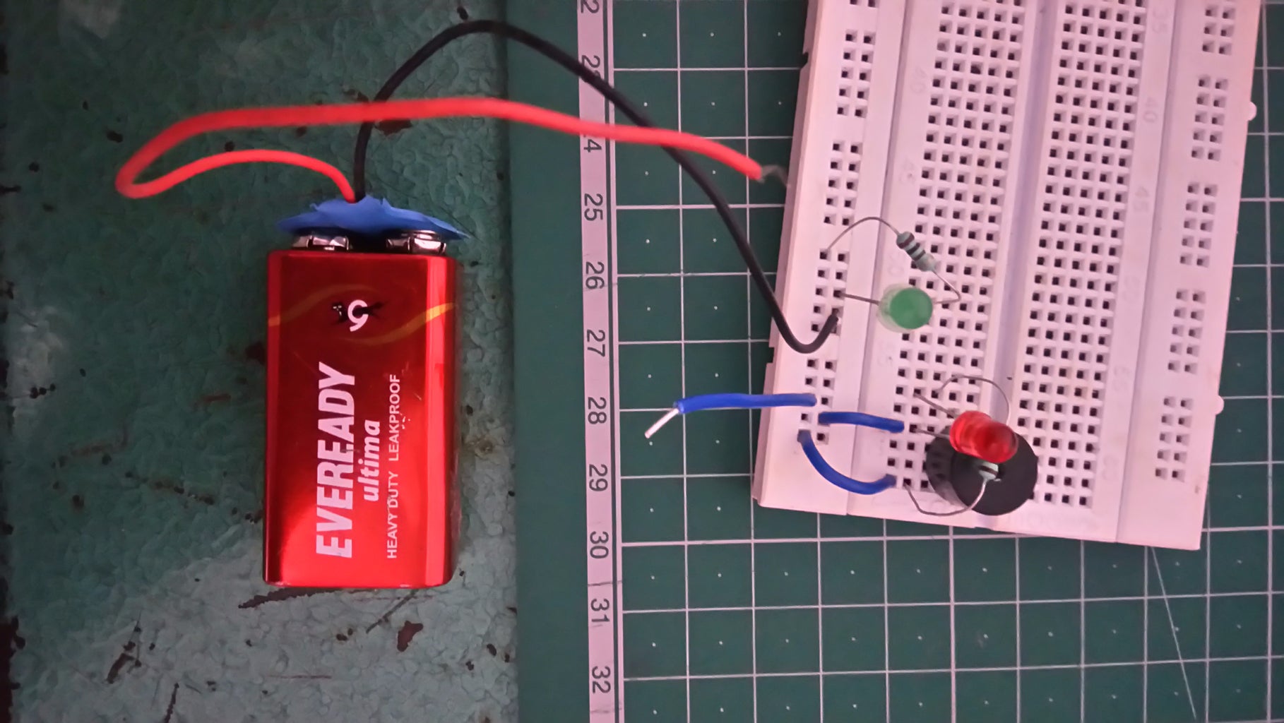
The most important part of any build is to test your circuits. Use a breadboard, Test the circuit and then you're off to prototyping!
I have added the circuit diagram in the picture above.
Apparently due to technical issues, I couldn't upload the video of the prototype of my continuity tester so please bear with me in this instructable.
Optional Update :
You could add a 5V regulator to the above circuit if you'd want to make the LEDs survive for longer period.(I didn't do that as my battery had dropped its voltage to roughly about 5V)
Step 3: Make It Permanent!

Solder the components according to the circuit diagram and then you're done!
(I actually forgot to add probes to this circuit so that I could connect them to any circuit and test it.)
This circuit was a great build and it works like a charm.
Consider supporting me on patreon and follow me YouTube, if you want some more updates on my projects!
Thanks For Reading!
Post Plans:
I have plans of embedding this circuit in the next project, So stay tuned for that!!!
That's all for today FOLKS! Have a nice day!


