

Introduction: Arduino Based Binary Alarm Clock


Hey,
today i would like to show you how to build one of my latest projects, my binary alarm clock.
There are a ton of different Binary clocks on the internet, but this might actually be the first one, made from a strip of colorful addressable LED's, that also features an alarm function and touch buttons, to set things like the time and the color.
Please don't let the complicated look of it scare you away. With a little explanation, reading binary is actually not as hard as it seems. And if you are willing to learn something new, i would like to help you in doing so later on.
Let me tell you a little bit about the story behind this project:
I originally planned to build a "normal" clock, that uses LED's as it's hands, but i did not have enough LED's at hand.
Sooo, what do you do when you want to display the time with as few LED's as possible?
You go binary, and that is exactly what i did here.
This clock is the third version of it's kind. I built a very simple prototype right after the project idea hit me and took it to the Maker Faire in Hannover, to see what people think about it. While i was there, i received a lot of very positive and interesting feedback as well as improvement ideas.
The result of all those ideas and hours of thinking, tinkering and programming, is this rather interesting looking little alarm clock, that has many more features than version 1.0 and today we are going to go through every step of the building process, so you can easily build one yourself.
There is also a very detailed Video over on Youtube, in case you do not wan't to read everything.
Step 1: Get Your Stuff


Here is a little list of all the components and tools, that you are going to need to build your own binary clock.
Electronics:
- 18 adressable Ws2811 LED's (e.g. Neopixels) on a strip with 60 LED's per m (ebay)
- Arduino Nano (with ATMega328 processor) (ebay)
- 1307 RTC module (ebay)
- 4X Capacitive touch buttons (ebay)
- bs18b20 digital temperature Sensor (ebay)
- LDR (ebay)
- laptop/smartphone speaker or piezo buzzer
- 2222A NPN transistor (or something similar)
- male headers
- angled female headers(ebay)
- 1kOhm resistor
- 4,7kOhm resistor
- 10kOhm resistor
- Wires
- 7x5cm prototyping PCB 24x18 holes(ebay)
- silver wire (jewellery wire) (ebay)
- 90° mini usb adapter (ebay)
Other materials
- Vinyl wrap
- 4X 45mm m4 flange head screws (ebay)
- 32X m4 metal washers
- 4X m4 lock nut
- 28X m4 nut
- 4X 10mm m3 brass PCB standoff (ebay)
- 8X 8mm m3 screw (ebay)
- sheet of aluminum
- 2 mm sheet of milky acrylic
- 2mm sheet of clear acrylic
- 3 mm sheet of MDF
- double sided tape
Tools
- mini USB cable
- computer running the Arduino IDE
- 3,5 mm drill bit
- 4,5 mm drill bit
- power drill
- cutting knife
- coping saw
- soldering ion
- metal cutting scissors
- file
- sand paper
Templates (now with dimensions)
Code


Step 2: Cut the Front and Rear Panel


The first piece we are going to make is the acrylic front panel. We mark where we want our cuts to go, while keeping in mind, that we want a little bit of tolerance for sanding. Then we simply scrape the acrylic with our cutting knife. After we have done that for 10 to 20 times we have a groove. We can then place that grove on the edge of a table and bend the acrylic until it breaks.
After the front panel is cut to size we cut the back panel out of a piece of MDF. We can use our coping saw for this but a cutting knife does also work. We just have to clamp the MDF onto a scrap piece of wood and scrape it with our cutting knife until the blade goes through and we have two individual pieces.
Now we sandwich the two panels together and sand each side to perfectly allign.
After this is done, we cut out the first template and put it onto the two panels using some tape and start drilling the marked holes.
First we drill a 4,5 mm hole into each of the 4 corners. As the acrylic is very brittle and we don't want it to break, we will start with a small drill bit and work our way up until we reach the desired hole diameter. Then we use the template to sand the corners to the right shape.
Step 3: Finish the Rear Panel


For now, we can put the front panel aside and stick the second template onto the back panel, where we need to use a 3,5mm drill bit to drill the holes for our 4 pcb standoffs, as well as 4 holes that mark the edges for the little back window.
We then use our coping saw to cut the window out and smooth the edges, with a file. You also don't want to forget to drill the hole for the mini USB cable (I heard of one not so focused maker, that tends to to do such things:D) .
As we are now finished cutting the back panel we can proceed to wrap it in vinyl wrap. We simply cut two pieces to the right size and apply the first one to one side. Then we cut the rims away and free the window. A hair dryer can help to make all of the holes visible again, so we can also cut them out. After doing the same thing for the other side we use our next template and our scrape and break technique to make the little acrylic window for our back panel.
Step 4: Make the LED Panel


Now we come the highlight of this project, in the most literal sense. The LED Panel.
We use our metal cutting scissors to cut a 12,2cm by 8cm piece out of a sheet of metal. Be careful while doing this, as the scissors create very sharp edges. We are going to smooth those with our file and some sandpaper. Then we add our next template to drill holes for the screws and the wires.
Time to prepare the actual LED's.
First, we cut them into three strips of 6 LED's each. Some of the LED strips come with a very thin adhesive layer or no adhesive at all, so we are going to stick our strips onto a piece of double sided tape and cut it to size with a knife. This will make it stick to the metal plate and, although this is not a professional solution, will insulate the copper pads from the metal surface underneath.
Before we actually stick the strips onto the panel, we clean it with alcohol. While we attach the LED's, we have to make sure that we put them down in the right place as well as in the right direction. The little arrows on the LED strip indicate the direction, in which data travels through the strip.
As you can see in the fifth picture, our data line comes from the top left corner of the panel, goes through the first strip all the way to the right side, than back to the beginning of the following strip on the left and so on. So all of our arrows have to point to the right side.
Let's heat up our soldering ion and put some tin onto the copper pads, as well as onto our wire. The data lines are connected as i just described, while we simply hook the plus and minus pads of the strip up in parallel.
After the strips are wired up, we use our knife to carefully lift the ends of each strip while holding the LED's down, so they still point upwards. Then we put some hot glue underneath to insulate our soldering joints.
After this is done and, we add a few header pins to the wires that go to the PCB. Those wires should be about 16cm long. To be extra sure, that the metal panel is not shorting anything, we use a Multimeter to measure the resistance between all of the pins. If it shows anything above 1kOhm, everything is fine.
Now we can hook it up to an Arduino, run a strandtest and enjoy the colors.
Step 5: Make a Light Guide


If we put our led panel right behind the milky acrylic, it can become quite tricky to tell individual LED's apart. This would make our clock even harder to read, than it already is.
To solve this issue, we are going to make ourselves a little light guide. For this we simply cut out another piece of MDF, that has the same size as the front panel. Then we add yet another template to it and drill eighteen 3,5mm holes for the LED's, as well as four 4,5 mm holes for the screws into it. We can then clamp it down to the front panel and use some sandpaper to align the two.
As you can see in the last picture, the light appears a lot more focused now.
Step 6: Make the Button Frame


The last enclosure component, that we are going to make, is the button frame.
We, ones again, cut a piece of MDF to the right size and add a template to it, then we drill all the necessary holes and use our coping saw, to cut out the middle section.
Our frame is supposed to hold the 4 touch buttons, the light sensor and our little speaker in place. Before we can attach them to the frame, we cut a couple of smaller cover pieces out of MDF. We then hot-glue our components onto those covers and add wires to them.
The touch button's power pads are hooked up in parallel, while each output line gets an individual wire. This is also a good moment to test if they are all working. As the light sensor needs 5 Volts on one side, we can simply hook it up to the alarm buttons VCC pad and solder a wire to the other leg.
After the panels are prepared, we cut into the sides of the frame, to make room for them and their wires.
Then we remove the wood dust from all of the pieces with a vacuum cleaner and cover them in vinyl wrap.
We use the precision knife to remove pieces of the vinyl, directly above the sensitive areas of our touch modules. With some double sided tape, we can than attach our own buttons to the MDF. I made my buttons out of rubber foam, which gives them a nice, soft texture, but you can use any non-metallic material you want.
On the frame we use our knife to free a little bit of the MDF again, Which gives us a grippy surface for the hotglue. Then we can finally glue the components to the sides of our frame.
Step 7: Solder the Main PCB


Lets leave the frame as it is right now and move on to the the PCB. You can see the PCB layout in the first picture.
We start by placing the components with the lowest profile on the circuit board. The smallest components are the wire bridges, which i remembered a little bit too late, so i started with the resistors. We solder our components in place and move on to the next higher set of components.
Next up we have our female header pins. To save some space and to be able to plug our electronics in from the side we mount those in a 90 degree angle.
Transistors do not really fit the 2,54mm hole spacing of our PCB, so we use our pliers to carefully bend their legs to the shape, shown in the second picture. We first solder one of their legs in place and turn the PCB around. We then reheat the soldering joint and use our finger or a pair of pliers to properly position the component. Now we can solder the other two legs in place.
After all of the small components we solder our Arduino and our real time clock module in place. The RTC module does also not fit the hole spacing that well, so we are only going to equipt the side, that has 7 soldering pads with header pins. We furthermore place some tape underneath it, to prevent any short circuits.
As all of our components are soldered in place, it is now time to make the connections on the other side of the board. For this we are going to take out our non insulated wire. A pair of pliers can be used, to straighten it. Then we cut the wire into smaller pieces and solder it to the PCB.
To make a connection we heat up a soldering joint and insert the wire. We then keep the soldering ion on it, until it reaches the right temperature and the solder encloses it and we get a joint, that looks like the one in the picture. If we don't heat up the wire, we might end up with a cold joint, which would look similar to the other example and does not conduct very well. We can use our wire cutter, to push the wire down while soldering and make sure that the it is laying flat on the PCB. On longer connection paths, we solder it to a single pad every 5 to 6 holes until we reach a corner or the next component.
In a corner we cut the wire above the first half of a soldering pad and solder the end to it. We then take a new piece of wire and go on from there in a right angle.
Making those blank wire connections is quite tricky and takes some skill, so if you are doing this for the first time, it is definitely not a bad idea to practice it on a scrap PCB, before attempting to do it on the real one.
After we are done soldering, we check the connections again and make sure that we did not produce any short circuits. Then we can put the PCB inside the button frame and use it as a reference for the necessary frame wire lengths. We then cut those wires to the right length and add male header pins to them.
All the 5V and ground connections of the touch buttons come together into a 2pin connector, The 4 output wires get a 4pin connector and the light sensor line as well as the two speaker wires merged into a three pin connector. Dont forget to mark one side of each socket and connector with a sharpie, or some tape, so you don't acidentally plug them in the wrong way.
Step 8: Assemble the Clock


After this I went back to the front panel and carefully applied a sticker, made out of transparent laser printer foil, as a final touch.
Even though i applied it very carfully, i was unable to get a bubble free result, which is unfortunately clearly visible upon closer inspection. The foil does also not stick to the corners very well, so i can not really recommend this solution.
It could probably be done with a better sticker, or , if you are good at drawing, you could add the numbers with a sharpie.
Now we have all of the components and can assemble our clock.
We start by putting the light guide and the front panel together. After all 4 bolts are in, we align the two panels and then tighten them. A couple of nuts later comes the light panel, where we have to take a look at the direction. The cable should be at the top.
The third piece, is the button frame. Keep in mind that, when looking from the front side, it's speaker should be on the right side of the clock. Pull the cable of your led panel through the middle of the frame, before you fix it in place.
Now we put the front assembly asside and move on to the back panel. In the picture, you can also see my beautiful self made 90 degree mini USB Adapter. I linked you a proper adapter, so you wont have to deal with this kind of mess. You can simply plug your adapter in and run the cable through a hole in the rear panel.
We take our M3 screws and our PCB spacers, to fix the little window. It is important to carefully tighten the screws, as we don't want to damage our acrylic. Then we take our PCB, plug in our adapter and screw it onto the spacers. The component side should be facing the window, while the Arduino's USB port faces the bottom of the clock.
Then we plug all of the connectors from the front assembly in, while keeping the polarity in mind and carefully squeeze all of the wires into the clock. We can then close it up with the back panel and tighten the 4 remaining lock nuts.
In the end, you want to have a washer on every side of each panel, while the light guide is placed directly behind the front panel. We have one nut between the light guide and the led panel and two more, separating it from the button frame. You can also see that in the last picture.
As i used short bolts with a length of 40mm, i only have 3 nuts keeping the back panel and the frame apart. With the right 45 mm bolts, you would add another nut here, as well as one or two extra washers. On the end of the assembly we have our lock nut, so that everything stays in place.
Step 9: Upload the Code and Calibrate the Light Sensor


Time to upload our code.
First we download all of the necessary files and unzip them. We then open our Arduino libraries folder and drop all of the new libraries into it.
Now we open the light sensor calibration sketch, which will get us the bright and dark values for the clock's automatic dimmer function. We upload it, open the serial monitor and follow the instructions on screen.
After that is done we open the binary clocks actual code and replace the two values with the ones we just measured.
We close all other windows, upload the code to our clock and we are done.
Time to play around with our new gadget.
Step 10: A Quick Introduction to the Binary System


Before we go on i would like to answer the one question that has probably already gone through your mind,
"How in the world do you read this clock?"
Well, for this i would like to give you a short introduction to the binary system.
We are all familiar to the decimal System, where each digit can have 10 different states, ranging from 0 to 9. In binary each digit can only have two states, either 1 or 0 that's why you can use something as simple as an led to display a binary number.
To display numbers that are grater than 9 in decimal, we add more digits. Each digit comes with a certain multiplier. The first digit from the right comes with a multiplier of 1 the next one is 10 and the next one is 100. With each new digit the multiplier is ten times as big as the one of the digit before. So we know that the number two placed one digit to the left, represents the number 20. While two digits to the left, it represents 200.
In the binary system each digit also comes with a multiplier. However, as each digit can only have two different states, each new multiplier is two times as big as the previous one. Oh and by the way, binary digits are called Bits. So let's take a look at our first example, if we place a 1 at the lowest position it is a simple 1, but if we place it on the next higher position, where our multiplier is 2, it represents the number 2 in binary.
How about the slightly more tricky example on the bottom of the picture. The third and the first bits are on. To get the decimal number that is represented here, we simply add the values of the two bits. So 4 * 1 + 1*1 or 4+1 gives us the number 5.
8 bits are referred to as a byte, so let's see what number we get if we fill a whole byte with ones. 1+2+4+8+16+32+64+128 that is 255 which is the highest value a single byte can have.
By the way, while in the decimal system the digit with the highest multiplier always comes first, you have two ways of writing a number down in binary. Those two methods are called least significant byte first (LSB) and most significant byte first (MSB). If you want to read a binary number, you have to know which of the two formats is used. As it is closer to the decimal system, our binary clock uses the MSB variant.
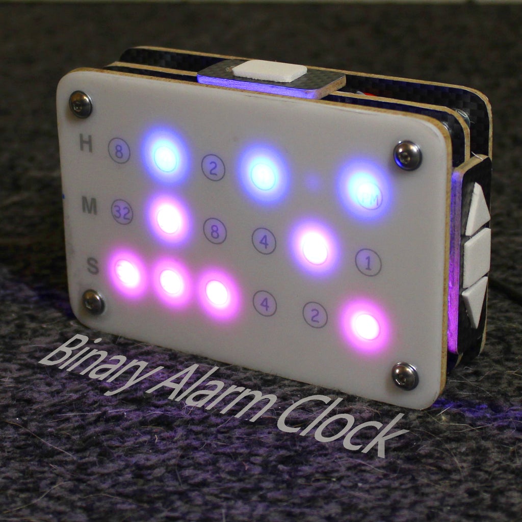
Lets get back to our real world example. As highlighted in the sixth picture, our clock has 4 bits to display the hour. Than we have 6 bits for the minute and also 6 bits for the second. Further more we have a single am/pm bit.
All right, tell me what time it is in the 6th picture, than skip to the last one . . ....
in the hour section we have 2+1 which is 3 and the pm bit is on so it is evening. Next up the minute 32+8, that is 40. For the seconds we have 8+4+2 which is 14. So it is 3:40:14 pm or 15:40:14.
Congratulations, you just learned to read a binary clock. Of course it takes some getting used to and in the beginning you will have to add the numbers together, every time you want to know what time it is, but similar to an analog clock without a dial, you get used to the LED's patterns over time.
And that is part of what this project is all about, taking something as abstract as to the binary system into the real world and getting to know it better.
Step 11: Using the Binary Alarm Clock


Now we finally want to play around with the clock, so let us take a quick look at the controls.
The software can distinguish between a single button tap, a double tap and a long tap. So each button can be used for multiple actions.
A double tap on the up or down button changes the LED's color mode. You can choose between different static and fading color modes as well as a temperature mode. If you are in one of the static color modes, holding the up or down button changes the color . In a fading mode, a single tap alters the animations speed.
To set the dimmer mode, you double tap the ok button. The led panel indicates the set mode by blinking multiple times.
- One time means no dimmer.
- Two times means the brightness is controlled by the light sensor.
- Three times and the LED's automatically turn off after 10 seconds of inactivity.
- Four times and both dimmer modes are combined.
Long pressing the ok button will brings you into the time setting mode, where you can use the up and down arrows to alter the number. A single tap onto the ok button brings you from the hours to the minutes, one more tap and you can set the seconds. After that, one last tap saves the new time. If you accedentialy enter the time setting mode, you can simply wait for 10 seconds and the clock will automatically leave it.
As with the ok button, long pressing the alarm button lets you set the alarm. Double tapping the alarm button activates or deactivate the alarm.
If the clock is ringing, you single tap the alarm button, to send it to sleep for 5 minutes or hold it, to deactivate disarm the alarm.
These were all of the functions the clock has so far. I might add more in the future which you can get, if you download the latest firmware version.
Step 12: Understanding the Code (optional)

I know that many people do not like programming very much. Luckily for those people, next to no programming knowledge is required to build and use this binary clock. So if you don't care about the programming side, you can simply skip this step.
However, if you are interested in the coding part, i would like to give you a general overview of the program.
Explaining every little detail of the clocks code would be an Instructable on it's own, so i will keep it simple by explaining the program in an object oriented way.
In case you don't know what that means, object oriented programming (OOP) is a concept of most modern programming languages such as C++. It allows you to organize different functions and variables into so called classes. A class is a template from which you can create one or multiple objects. Each of this objects gets a Name and it's own set of variables.
For example, the clock's code uses a couple of MultiTouchButton objects such as the alarmButton. Those are objects from the class MultiTouchButton, which is part of my Button library. The cool thing about those objects is, that you can interface with them similar to real world objects. For example, we can check, if the alarm button was double tapped by calling alarmButton.wasDoubleTapped() . Furthermore, the implementation of this function is nicely hidden in a different file and we don't have to worry about breaking it, by changing anything else in our code. A quick entry into the world of object oriented programming, can be found on the Adafruit website.
As you can see in the graphic above, the clocks program has a bunch of different objects.
We just talked about the button objects, which can interpret input signals as a tap, a double tap or a long press.
The jukebox, as the name suggests, can make noise. It has several melodies, that can be played through a small speaker.
The binaryClock object manages time and alarm setting, as well as alarm watching. It furthermore get's the time from the rtc module and converts it into a binary information buffer for the ledPanel.
The colorController encapsulates all of the color effect functions and provides the colorBuffer for the ledPanel. It also saves it's state in the Arduinos EEProm.
The dimmer takes care of the clocks brightness. It has different modes that the user can cycle through. The current mode is also saved in the EEProm.
The ledPanel manages different buffers for the color value, brightness value and binary state of each LED. Whenever the pushToStrip() function is called, it overlays those and sends them to the led strip.
All of the objects are "connected" through the main (the file with the setup and loop functions), that only includes a couple of functions to perform 3 essential tasks.
- Interpreting user input - It get's the input from the 4 button objects and puts them through a logic. This logic checks the current state of the clock to determine, if the clock is in normal, time setting or ringing mode and calls different functions from the other objects accordingly.
- Managing communication between objects - It constantly asks the binaryClock object, if it has new information available or if the alarm isRinging(). If it has new Information, it gets the informationBuffer from the binaryClock and sends it to the ledPanel object. If the clock is ringing it starts the jukebox.
- Updating objects - Each of the program's objects has an update procedure, that is used for things like checking inputs or changing the LED's colors. Those need to be called repeatedly in the loop function in order for the clock to work properly.
That should give you a general understanding of how the individual pieces of code work together. If you have more specific questions, you can simply ask me.
As my Code is definitely far from perfect, i will further improve it in the future, so a few functions might change. The cool thing about OOP is, that it will still work in a very similar manner and you can still use the graphic to understand it.
Step 13: Final Words

I am glad that you kept reading to this point. That means that my project was not too boring:).
I put a ton of work into this little clock and even more work into all of the documentation and the video, to make it easy for you, to build your own Binary alarm Clock. I hope my effort was worth it and i could hook you up with a great idea for your next weekend project or at least, give you some inspiration.
I would love to hear what you think about the clock in the comments below:).
Even though i tried to cover every detail, i might have missed a thing or two. So feel free to ask, if there are any questions left.
As always, thank you very much for reading and happy making.

Runner Up in the
LED Contest 2017

Participated in the
Arduino Contest 2017

Participated in the
Epilog Challenge 9


