

Introduction: Power Bank Inside a USB Cable


In this instructable I show you how to make power bank hidden inside USB cable. Main point of this project, make cable witch can jarg small devices such as: smartwatches, wireless headphones or prank your friends also save data transferring capabilities.
Parts for this project you can find lying in your house, for example: reuse broken USB cable, battery from old Bluetooth headset or tiny RC helicopter, salvage charging board from chip single cell power bank (today you can find them almost everywhere). Lets go Started.
Step 1: Prepare All Necessary Tools

- Soldering Iron;
- Soldering Wire;
- Desoldering Wire;
- Hot Glue;
- Prying tool;
- Set of Files;
- Multimeter;
- Scissors (Wire Cutters);
- Stationery Knife;
- Electrical Tape;
- Heat Shrink Tubes;
- Tweezers.
Step 2: Prepare All Necessary Parts


- USB Step UP power cable or USB Project box;
- USB micro B, Type C, Lightning cable (based on your needs);
- Power bank bord “T3845-I” ver. 1.0 or analogs;
- Tiny two position slider switch;
- Tiny Li-Po battery USB Type A male connector
Step 3: Remove Cable From the Case


You can skip this step if you already have suitable USB project box.
This is peaty easy, just find right spot, on the front of the connector and pry a little beat, than simple do rest following seam belong two parts. For this you’ll need guitar pick shape prying tool.
Step 4: Remove USB Connectors From the Power Bank Board

This is very complicated step.
First remove USB type A female connector.
- Remove as much solder as you can can from main contact points, for this you’ll need desoldering wire;
- Pick Stationery Knife or a piece of soda can and place it between board and connector, like on the photo below.
Second, remove micro USB type B female connector. This is most difficult because connector glued to the board with very strong adhesive.
- First remove all solder from main connectors using desoldering wire;
- Second heat up whole connector and try gently pull it up;
- If you can’t remove connector in one piece easily, simply cut it in small pieces using side cutters.
If you remove soldering pads, don’t be scary because board shares ground and you also can find positive (main) signal from one of the capacitor lag. See photo.
Step 5: Board Preparation


Notice! Some important traces located close to edges of the board, pay attention to not cut them completely.
For this step you’ll need a set of files.
All necessary cuts you can see on photos.
Step 6: Cut Case to Fit Power Bank Board


Because space inside the case very small and we save traces instead of shaving them and replacing with jump wires, we need some extra space to fit our board also cut off for slider switch.
For this step you’ll need: Stationery Knife and Files pair of protective gloves also necessary.
Dimensions and positions for cuts you can see on photos.
Step 7: Soldering


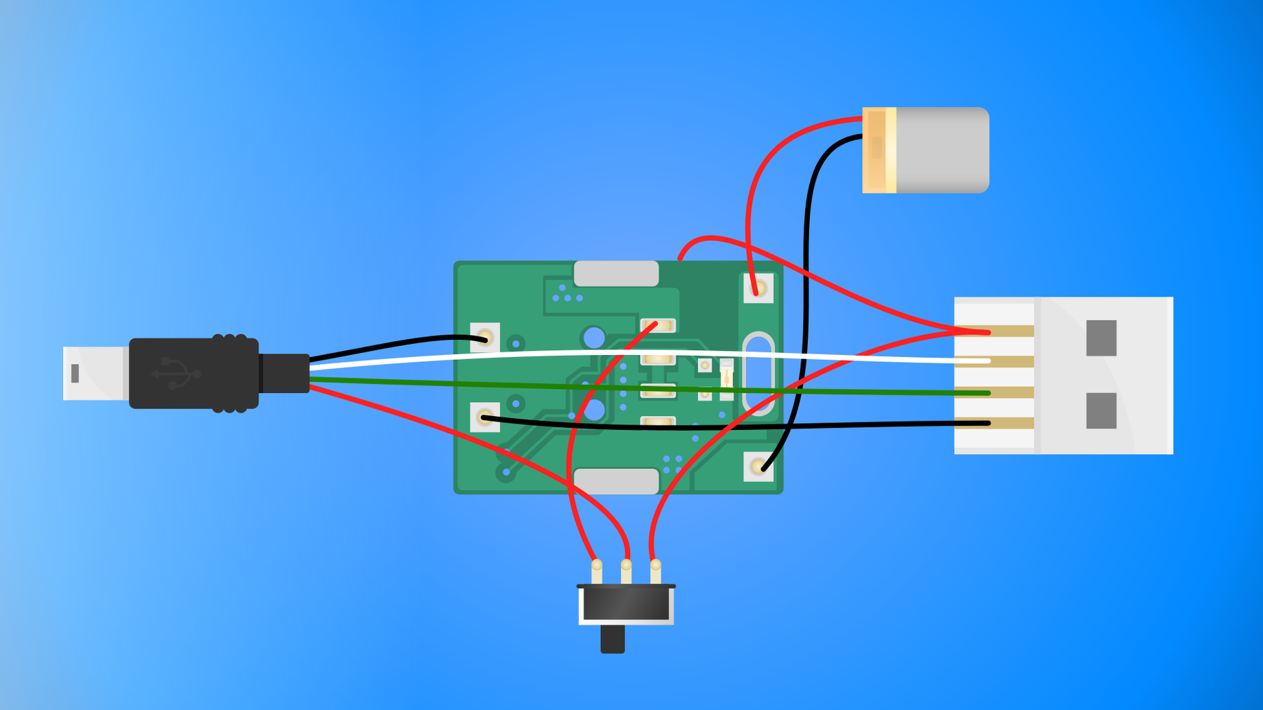
Now when we prepare our board and case time to solder all main components together.
- First of all remove USB type A female connector from the cable and strip outer jacket, ruffly 50mm in length.
Black wire is ground, red positive, green and white data wires.
- Put cable gland. You can reuse one from SteUp Power cable;
- Put heat shrink tubes on data wires;
- Soldering positive wire from USB cable to central of slider switch, also don't forget put heat shrink tube before soldering;
- Soldering another switch leg to the power bank positive out pad (see on the photo);
- Twist two wires together and solder one to the USB type male connector another to the slider switch.
This allows you switch between battery and USB power.
- Soldering second end from twisted wire assembly to the board positive contact pad;
- Now we can solder ground, because it shared all over the board you can strip ground wire a little bit in the middle and solder to the ground pad on the board and to the USB type A male connector;
- And last one solder battery to the board. You can find soldering points appropriately marked on the board itself.
Step 8: Assembling

Because USB connector very fragile it is good idea to simply hot glue it to the case with a switch. The rest of the assembling process is easy, just place our assembly inside, align and close, that ia all.
Step 9: Testing


Now let's go and test what we made.
As you can see we can get 5V out, data transfer also work just fine.
Step 10: Conclusion
Here I must to say, because battery has low capacity it hard to use with moder smartphones which requires a ton of energy This power bank can definitely give some juice to the smartphone but only very small amount in the same time this can be useful for small devices, such as: Bluetooth headphones, wireless mouses, smartwatches, fitness trackers you can even power Arduino with it.
Nevertheless this project proves that today's battery capacity or better to say size to capacity efficiency is not enough to power smartphone.

Participated in the
Pocket-Sized Contest

Participated in the
Trash to Treasure


