

Introduction: Computer Controlled Christmas Lights With Arduino


Have you driving by houses with fancy Christmas lights, often synchronized to music? Normally, these setups require commercial light controllers costing hundreds of dollars, commercial animation software that can also be quite expensive, a literal money pit for the average home owner.
This instructable shows you how to build a low-cost light controller using an Arduino. This controller animates strings of inexpensive lights found on Amazon, eBay, and lot of other online stores. The animations are created using the free xLights program. And the best part? Your lights are connected to your home wired or wireless network, so you can place your lights anywhere in the house or in the yard, controlled and animated from the comfort of your computer!
The beauty is once you create multiple controllers as you add more lights to your house, xLights makes them all work together as a "show". You can do all of the wonderful animated lights that the professionals use, with a little bit of homemade building!
This instructable will build one light controller than can animate up to 200 lights. You can buy strings of lights to hang on a tree, or push the lights into "coro", a white plastic resembling cardbaord) in prepade shapes such as stars, candy canes, and more. You can put lights into tube for glowing arches, attach them to strips to make virtual trees, and so much more.
You'll be amazed how easy it and have the best Christmas (and other holidays) lights on the block!
You can also visit my website www.itwinkle.org for much more information on building computerized Christmas lights.
.
Let's get started...
Step 1: Stuff You Need to Buy


Here is what you’ll need to build computerized, animated lights with Arduino:
Arduino Mega 2560
This is the "brain" of the light controller. It is a low-cost microcomputer (basic computer) that can be programmed to do almost anything. It should come with a USB Type B cable for connecting to your computer. This looks like a printer USB cable.
Buy it here: https://www.amazon.com/keyestudio-development-boar...
Arduino network board
This enables the Arduno microcontroller to communicate on your home computer's network. This way you can create animations on your computer/laptop which sends commands to the Arduino via Ethernet to animate the lights.
Buy it here: https://www.amazon.com/HiLetgo-ENC28J60-Ethernet-...
Male-to-female jumper wires
These are needed for connecting the Arduino microcontroller to the network board, among other things
Buy them here: https://www.amazon.com/Foxnovo-Breadboard-Jumper-...
Male-to-male jumper wires
These are needed for connecting the Arduino microcontroller to the buck converter among other things.
Buy them here: https://www.amazon.com/GenBasic-Solderless-Ribbon-...
1-4 sets of 12V WS2811 lights (50 bulbs each set)
These are digital lights that are animated with an industry standard protocol called ws2811. Your Arduino, once programmed, will also know this protocol. These lights come in many shapes & sizes. As long as they support ws2811 or ws2812, they will work with your project. Make sure the lights operate on 12V DC and that the wire thickness is 20 AWG or lower. This ensures that the lights can be placed at far distances from your controller. You can have a maximum of four 50-bulb strings per Arduino (200 bulbs) to the controller
Buy them here: https://www.amazon.com/Rextin-WS2811-Digital-Addr...
"Coro" plastic shapes
You can arrange your strings or lights any way that you want (hang them, put them on a tree, etc.). One popular way is to push them into plastic cardboard-like shapes like these:
Buy shapes here: https://www.boscoyostudio.com/index.php?main_page=...
12V power supply (enough for 50-200 lights)
This power supply will power your Arduino and up to four strings of lights.
Buy it here: https://www.amazon.com/LEDMO-Switching-Converter-...
Buck converter
The Arduino works best at 7V. This buck converter allows your power supply to supply 12V to the lights and 7V to the Arduino from the same power supply.
Buy it here: https://www.amazon.com/RioRand-3-01-0076-Converter...
Extension cable
You'll need to run a extension cable between your Arduino to where the lights will be placed in your house and/or yard. To build this cable, you'll need thick Ethernet cable (I recommend 23 AWG for the wire thickness) and 3-pin connectors on each end.
Buy Ethernet cable here: https://www.monoprice.com/product?c_id=102&cp_id=1...
Buy indoor connectors here: https://www.ebay.com/itm/5-pairs-of-3-pin-JST-SM-c...
Outdoor enclosure
If you plan to keep your Arduino and your lights outside, you'll need a weatherproof box, some weatherproof connectors, and other gear. Here is one idea. This will protect the strings, network cable, and power cable going into your outdoor enclosure.
Buy a plastic box to hold the Arduino, power supply, and network board at Walmart or a dollar store
Buy outdoor (weatherproof) 3-pin connectors here (instead of the indoor connectors above): https://www.amazon.com/dp/B01EMFU30U
Buy small cable glands here: https://www.amazon.com/Yongcun-Black-Glands-Waterp...
Buy large cable glands here: https://www.amazon.com/Yongcun-Nylon-Glands-Waterp...
Power cable
Any 3-prong power cable (18 AWG) will do. You can use an existing computer/monitor power cable for this.
Ethernet cable
This cable connects your Arduino to your home computer network via a wireless router, network hub, or network switch. This allows your computer/laptop to "see" your Arduino via your home network. This cable can be up to 300-feet long.
If you intend to connect your Arduino direclty to your computer/laptop (and not your home network), you may also need an Ethernet hub, switch, and/or an Ethernet crossover cable. This is explained more later on.
Step 2: Stuff to Help With Building

This equipment will certainly come-in handy while you are building your Arduino light controller!
- Heat shrink tubing
- Heat gun, blow dryer, cigarette lighter, or stick lighter (for melting heat shrink tubing)
- Jumper wires with alligator clips (useful for troubleshooting problems)
- Fork or ring crimp-on connectors (for attaching wires to the power supply)
- Crimper tool for above connectors
- Soldering gun/iron & solder
- Electrical tape
- Craft/utility knife
- Wire cutters
- Wire stripper
- Pliers
- Voltmeter
- Jeweler's (or very small) flat-blade screwdriver
- Zip ties
Step 3: Connect Buck Converter to Power Supply


The Arduino works best with 7V of power. Since we are using a 12V power supply to power the lights, the buck converter will lower the voltage going to the Arduino.
- Take a red male-to-female jumper wire and cut-off the female end. Strip the exposed end, then crimp a fork connector onto it.
- On the male-pin end of this wire, bend the pin in-half with pliers, then hook into the "In+" hole on the buck converter. Solder this pin into place. On the fork end of this wire, attach to one of the V+ terminals on the power supply.
- Create a second wire (black) as above. Hook into the "In-" hole on the buck converter. Solder this pin into place. On the fork end of this wire, attach to one of the V- terminals on the power supply.
Step 4: Attach Power Cord to Power Supply


Note: Be very careful when connecting wires from the power cord to the power supply! Since we are working with AC voltage, incorrect wiring could cause a serious shock or fire. Do NOT plug the power cord into a wall outlet while performing the steps below.
- On the power cord, strip the insulation back until you see white, black, and green wires. Or the colors could be blue, brown, and green/yellow instead.
- Be careful that you do not damage the insulation on these three wires or a dangerous "short" can occur. If in doubt, start over, cut off the end of the cable and strip everything again.
- Crimp red fork connectors onto each of these three wires. Make sure that the fork connectors are tightly secure and do feel loose on the wire.
- Attach the white (or blue) wire to the N(eutral) terminal on the power supply. Attach the black (or brown) to the L(ine) terminal on the power supply. Attach the green (or green/yellow) wire to the ground terminal on the power supply. The ground terminal may look like an upside-down "wireless signal" symbol.
- Plug the power cable into the wall outlet. Be very careful not to touch the terminals on the power supply!
- Use a voltmeter to check the voltage on the -V terminal (black probe on voltmeter) and +V terminal (red probe on voltmeter). The voltmeter should read approximately 12V.
Note: If you connect other wires to the power supply, especially to power your light strings, make sure that the gauge is 18 AWG or thicker! Thinner wire may overheat and/or not provide enough power (voltage) to the string.
Step 5: Adjust Buck Converter Voltage

The Arduino works best with 7V of power. Since we are using a 12V power supply to power the lights, the buck converter will lower the voltage going to the Arduino.
- Take a red male-to-male jumper wire. On one end this wire, bend the pin in-half with pliers, then hook into the "Out+" hole on the buck converter. Solder this pin into place. Create a second wire (black) as above. Hook into the "Out-" hole on the buck converter. Solder this pin into place.
- With the power cable plugged into the wall and the power supply outputting power, use a voltmeter to test the power coming from the wires that you just created. Use a jeweler's screwdriver to turn the tiny brass screw on the buck converter. Turn it until the voltage starts to change. You may need to turn it a lot! Keep turning until the voltage reads approximately 7V.
Note: Do not provide less than 7V to the Arduino as it will cause it to crash/freeze while running the light controller software. If you provide more than 7V, the Arduino could overheat and eventually fail.
Step 6: Connect Buck Converter to Arduino
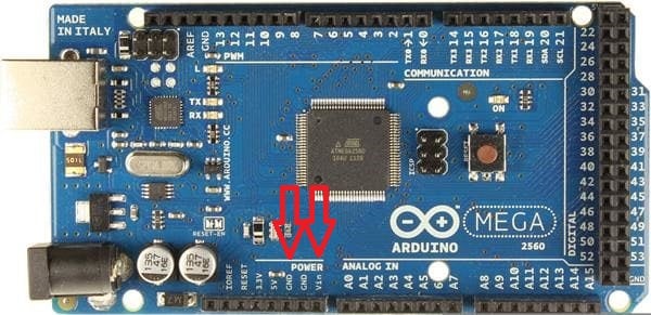

- Unplug the power cable from the wall.
- Connect the red wire from the Out+ terminal of the buck converter to the "Vin" terminal on the Arduino.
- Connect the black wire from the Out- terminal on the buck converter to the "GND" terminal on the Arduino.
Note that the Arduino has multiple GND terminals; you can use any of them.
That's it! Now you have provided power to the Arduino.
If you plug the power cord into the wall, the light on the Arduino should slowly blink off and on. This is the default program built into the Arduino when you first buy it.
Let's prepare the network board next.
Step 7: Connect the Network Board to the Arduino


The network board allows the Arduino to communicate on an Ethernet network. When you create light animations on your laptop, these animations are sent from your laptop to the Arduino via your home network via an Ethernet cable.
When you look at the network board, there are six rows of two pins. There is a legend above and below this block of pins. In the diagram show, "5V" in the legend corresponds to the first pin the first row, while "ST" refers to the second pin in the fourth row.
When you look at the Arduino, find the holes marked 50-53. These are in the lower-right corner of the Arduino. Also find, on the Arduino, the holes marked "5V" and "GND". There are along the bottom row of the Arduino.
Using the male-to-female jumper wires, connect the female ends to the network board and the male ends to the Arduino in this order:
- Network board "S0" to Arduino pin 50
- Network board "ST" to Arduino pin 51
- Network board "SCK" to Arduino pin 52
- Network board "CS" to Arduino pin 53
- Network board "5V" to Arduino "5V" pin
- Network board "GND" to Arduino "GND" pin
Note that the Arduino has multiple GND terminals; you can use any of them. Be sure not to connect wires for pings 52 & 53 to the bottom row in the lower-right corner of the Arduino! This bottom row is GND only.
The Arduino gets its power from the power supply (7V) while the network board gets its power from the Arduino (5V).
To test the network board, plug an ethernet cable into it, then the other end into a router, hub, switch, or to the Ethernet port on your computer/laptop. If you look at the network port on the network board, there should be a steady green light and an amber light that flashes intermittently. That is a good sign!
Note: Be careful when plugging jumper wires into your Arduino! If you bend the jumper wire pin, do not straighten the bent pin; throw away the jumper wire. A bent pin is weakened and can eventually break off inside the female socket in the Arduino.
Step 8: Create Extension Cables for the Lights


Most likely, your lights will be placed at a distance from the Arduino. For that you need to build extension cables.
The ws2811 lights that you purchased use three wires: power, ground, and data. But you can't simply use any three-wire cable for your extension cable. That's because the data wire can pickup interference from the power and ground in the same cable. To get around this problem, use a specially wired Ethernet cable for your extension cables.
Note: I recommend no longer than 50-60 feet for your extension cables using this method. Also, be sure that the Ethernet cable uses 23 AWG or thicker wire.
First, strip off the insulation on one end of the Ethernet cable. Then, strip the some insulation from all eight wires within.
You'll notice that there are four solid-color wires and four white wires (actually, mostly white with some color on them). Twist all four mostly white wires together. This will be our ground "wire". Then, twist the blue, brown, and orange wires together. This will be our power "wire". The remaining wire (green) will be our data wire. Repeat these steps for the other end of the Ethernet wire.
.
For indoor installations
If your Arduino and lights will be indoors, solder a male JST connector to one end of the Ethernet cable and a female JST connector to the other end.
- The red outer wire on the connector is soldered to the colored "power" wires on the Ethernet cable.
- The black (or white) outer wire on the connector is soldered to the white "ground" wires on the Ethernet cable.
- The middle wire (usually green) on the connector is soldered to the single green wire on the Ethernet cable.
.
For outdoor installations
If your Arduino and lights will be outdoors, use the 3-pin round outdoor connectors instead of the JST indoor connectors. Solder a male outdoor connector to one end of the Ethernet cable and a female outdoor connector to the other end.
- The red wire on the connector is soldered to the colored "power" wires on the Ethernet cable.
- The black wire on the connector is soldered to the white "ground" wires on the Ethernet cable.
- The yellow wire on the connector is soldered to the single green wire on the Ethernet cable.
Step 9: Connect a String of Lights to Your Extension Cable


For an indoor extension cable with JST connectors
Your lights should have come with JST connectors on both ends. Plug the female end of the lights to the male end of your extension cable. Easy! You can skip the instructions below and move to the next step.
If your lights came with no connectors on either end (bare wires), then you need to add a connector to the string. Figure out which end of the light string is the "input" end and which end is the "output" end. To do this, look closely at the first bulb on either end of the string. Each bulb has an "input" side and an "output" side. The input side is marked with "12V", "DI", and "GND" while the output side is not marked with these terms. A magnifying glass may help! The first bulb in the string is where the bare wires go into the "input" side of that bulb. On the other end of the string, the bare wires come from the "output" side of the last bulb. Make sense?
Connect a female JST connector to the three bare wires on the "input" side of the first bulb.
- The red outer wire on the connector is soldered 12V wire on the string.
- The black (or white) outer wire on the connector is soldered to GND wire on the string.
- The middle wire (usually green) on the connector is soldered to DI wire on the string.
Plug the female end of the lights to the male end of your extension cable.
.
For an outdoor extension cable with waterproof round connectors
Regardless if your strings came with JST connectors on them or not, you will need to cut off the connector on the "input" side of the string and solder in a waterproof connector instead.
Figure out which end of the light string is the "input" end and which end is the "output" end. To do this, look closely at the first bulb on either end of the string. Each bulb has an "input" side and an "output" side. The input side is marked with "12V", "DI", and "GND" while the output side is not marked with these terms. A magnifying glass may help! The first bulb in the string is where the bare wires go into the "input" side of that bulb. On the other end of the string, the bare wires come from the "output" side of the last bulb. Make sense?
Connect a female round waterproof connector to the three bare wires on the "input" side of the first bulb.
- The red wire on the connector is soldered 12V wire on the string.
- The black wire on the connector is soldered to GND wire on the string.
- The yellow wire on the connector is soldered to DI wire on the string.
Plug the female end of the lights to the male end of your extension cable.
Step 10: Connect Extension Cable to the Arduino and Power Supply


To interface your extension cable to the Arduino and power supply...
.
For an indoor extension cable with JST connectors
Crimp fork terminals to the red and black/white wires of a male JST connector. Solder the middle wire (usually green) on the JST connector to a male-to-male green jumper wire. Connect this adapter cable as follows:
- Attach the red wire with the fork connector to one of the V+ terminals on the power supply.
- Attach the black/white wire with the fork connector to one of the V- terminals on the power supply.
- Connect the male end of the green jumper wire to pin 29 on the Arduino. This is located near the top-right corner of the Arduino. Additional strings connect to pins 28, 27, 26, etc. (note: if pin 29 does not light up at the end of this instructable, try using pin 22 for the first string instead, then 23 for the second string, etc.).
.
For an outdoor extension cable with waterproof round connectors
Crimp fork terminals to the red and black wires of a male waterproof connector. Solder the yellow wire on the waterproof connector to a male-to-male green jumper wire. Connect this adapter cable as follows:
- Attach the red wire with the fork connector to one of the V+ terminals on the power supply.
- Attach the black wire with the fork connector to one of the V- terminals on the power supply.
- Connect the male end of the green jumper wire to pin 29 on the Arduino. This is located near the top-right corner of the Arduino.
Note: Be sure not to connect the green jumper wire to the top row in the top-right corner of the Arduino! This top row is 5V only and could damage your light string!
Step 11: Congratulations, You've Built the Hardware!

Whew, it was a lot of work, but now things get easier. You connected Arduino to the power supply, dropping down the voltage to Arduino friendly 7V through the buck converter. You built an extension cable for the string of lights, then made an adapter that connects the extension cable to the power supply and Arduino. Your work should look similar to the photo in this step.
It's a good idea to mount all of your hardware onto a wooden board (or to the bottom of your enclosure) so that this hardware doesn't jostle around. Foam tape works wonders for keeping things in-place!
Next, we learn how to program the Arduino to turn into a lights controller. Onto the next step!
Step 12: Install Arduino IDE


When you first received/bought your Arduino, there is a simple program on it that simply flashes an onboard LED. When you apply power to the Arduino, you will see the LED flash, telling you that the Arduino is working and running that program successfully.
We need to replace that simple program with a different program. This program will turn the Arduino into a light controller. It will receive commands from your computer/laptop then animate the string of lights connected to the controller). Technically, the Arduino will become a DMX to WS2811 light controller. The computer outputs DMX commands while your lights respond to WS2811 commands.
To put this special program (called a "sketch" in Arduino lingo) onto your Arduino, we need to install the Arduino IDE program on your computer first. Click this link to download the IDE.
Note: The light controller sketch does not work with the latest version of the Arduino IDE. The sketch only works with Arduino IDE version 1.6.5r2. The above link gives you the correct version. Note this download is for Windows based computers.
After downloading the IDE, unzip the file into a folder. Inside this folder you will see a file named Arduino.exe (or maybe just "Arduino"). It will have a blue, round icon next to it. Do not start this program yet.
Step 13: Install Light Controller Code (sketch)

Now that you have downloaded and unzipped the Arduino IDE program, the next step is downloading the light controller sketch. This is the program that will turn your Arduino into a light controller.
Thanks to my friend Keith for the sketch that turns an Arduino into a DMX light controller! But more than that, many thanks for being a friend through the years, working on Christmas lights together. I couldn't ask for a better friend!
You can download the sketch here. Unzip this file into a folder, apart from the Arduino folder that you made in the previous step. The folder should be named "DMXControllerWs2811". Please do not rename this folder; it must be named exactly that.
Inside this folder is another folder named "UIPEthernet". Move this folder to the Arduino folder from the previous step, to a folder named Libraries. So, you are moving the "DMXControllerWs2811\UIPEthernet" folder to inside the "arduino-1.6.5-r2\arduino-1.6.5-r2\libraries" folder. This step is necessary for the network board to work properly.
That's it! You have installed the light controller sketch onto your computer. The next step is configuring the sketch for your home network.
Step 14: Get the IP Address of Your Home Network

Your Arduino light controller will become a network connected device. As long as your Arduino is plugged into your router via an Ethernet, your computer/laptop will "see" it from anywhere in the house! Your laptop can be wireless or wired; it will still find your Arduino which is also connected to your network.
To teach the Arduino how to become part of your home network, we need to know the IP address of your computer/laptop. To do this on a Windows computer...
- Click on the Start menu and type cmd.
- When you see the cmd applications in Start menu panel, click it or just press enter.
- A command line window will open.
- Type "ipconfig" and press enter.
- You'll see a bunch of information, but the line you want to look for is "IPv4 Address." The number across from that text is your computer's IP address as four three-digit numbers with periods in-between (such as 100.150.200.250).
- We are interested in the first three sets of numbers. In the example, it's 100.150.200. Write down your specific "number" on a piece of paper.
- Close the command line by typing "exit" and press enter.
Step 15: Configure the Light Controller Sketch for Your Home Network

The next step is configuring the DMX program for your particular lights, such as the number of strings that are connected to the Arduino and the IP address that you will assign to the Arduino, which is important for your computer/laptop to "see" your controller. To do this, edit the global.h file in the DMXControllerWs2811 folder with your favorite text editor. These are the important lines that need changed:
.
#define UNIVERSE
A "Universe" is a number that represents all of the strings connected to your Arduino. In my case, I have two Arduinos, one set to universe 1 and the other set to universe 18. These numbers are defined in xLights. So when xLights is sending DMX commands to light-up strings in a particular universe, the Arduino is listening and acts upon commands only for its universe. If you don't know the universe for your particular controller, first read the section on setting up xLights on this website before continuing with these instructions.
.
#define MAXBULBS
If the strings of ws2811 lights connected to your Arduino have different number of bulbs on them, MAXBULBS indicates the number of bulbs on the longest string.
.
#define OUTPUTSTRINGS
This defines how many ws2811 strings are connected to the Arduino (a maximum of eight are allowed)
#define IP_BYTE_1 169
#define IP_BYTE_2 101
#define IP_BYTE_3 200
#define IP_BYTE_4 203
These four lines define the IP address for this Arduino. This way, xLights on your computer can "find" your Arduino on your Ethernet network and send DMX commands to it.
Replace IP_BYTE_1, 2, and 3 with the first three sets of 3-digit numbers that you wrote down from the previous step. For IP_BYTE_4, type "250". For instance, if your computer's IP address is 100.125.150.175, set IP_BYTE_1 as 100, IP_BYTE_2 as 125, IP_BYTE_3 as 150, and IP_BYTE_4 as 250.
Write down this IP address for your Arduino onto a label and stick it on your light controller. It’s a good idea to know what it is, in the future.
Step 16: Uploading the Light Controller Sketch to the Arduino

The next step is sending the light controller sketch to the Arduino's memory. To do this, open the folder that contains the Arduino IDE that you downloaded in previous steps. Then run arduino.exe. When the program starts, click File > Open, then browse to the DMXControllerWs2811 folder. Open the file named "DMXControllerWS2811.ino" or "DMXControllerWS2811".
Before connecting your Arduino to your computer, temporarily disconnect any lights that you have connected. Then connect the Arduino to your computer via a USB cable.
If this is the first time you have connected the Arduino, Windows will attempt to install hardware drivers for it. Depending on the version of Windows that you have and the brand of Arduino, the driver may install automatically or you may be prompted to provide the driver software (you may have to download the driver software for that particular brand of Arduino). Either way, the drivers must be installed successfully before proceeding to the next step.
Note: If Windows cannot automatically find drivers for your Arduino, you can tell Windows to manually find drivers in the "arduino-1.6.5-r2\drivers" folder.
When you connect the Arduino via USB and the computer accepts the connection with no errors (indicating that the drivers are installed and functional), tell the Arduino IDE the type of Arduino you are using.
- Click Tools > Board > "Arduino Mega or Arduino Mega 2560".
- Next, choose Tools > Ports > COM x where "COM x" is the virtual communications port that was assigned by the driver. If you see more that one listing under "Ports" and are not sure which one to choose, try the first one, then try uploading the DMX program as explained below. If the upload fails, choose the next COM port under Ports, then try uploading again.
- Next, verify that the sketch is valid by clicking the checkmark icon in the Arduino IDE toolbar (below the File menu).
- You will see "Compiling sketch..." in the window's lower status bar while the program is verified. This may take several moments.
If you see an orange message stating "Error compiling", then there is something wrong with the sketch or perhaps there is a typo in the global.h file that you modified in the previous step. In this case, you will need to close the Arduino IDE program, fix the problem, then open the Arduino IDE and try to verify the sketch again.
If the light controller sketch verifies correctly, you will see the "Done compiling" message in the status bar. At this point, you can upload the sketch to the Arduino via the Upload button (the right-arrow button next to the checkmark button in the toolbar). When you click Upload, the sketch will be verified again, then you will see "Uploading" in the lower status area. A light on your Arduino will rapidly flash during the upload process. When the upload is complete, you will see a message stating so in the status area. You can disconnect the Arduino from the USB cable.
Step 17: Testing the Lights
Now that your Arduino received the uploaded sketch, it is now a light controller! Let's see if your lights are connected properly.
- Disconnect the USB cable from the Arduino.
- Connect your lights to one end of the extension cord and the other end to your Arduino.
- Connect an Ethernet cable from the Arduino network board to your router, switch, hub, or into the Ethernet jack in your computer. This step is important!
- Plug the power cable into a wall outlet.
In a few moments, your strings should light up. All of the bulbs will go through a "self test", all changing at the same time to various colors. This means that the connections between your lights and the Arduino are correct and that the sketch that you uploaded is working properly.
After it goes through the seven basic colors, the lights will go dark. After a few moments. All of the lights will turn red and stay that way. This is normal. The red means that the Arduino is looking for commands from your computer, but we haven't set that up yet.
If your lights do not light-up, please refer to the Troubleshooting step near the end of this instructable.
Step 18: Testing the Arduino on Your Home Network


Now that your light controller is lighting up your lights, we need to see if the Arduino is communicating with your home network. This way we will know if your computer/laptop can "see" your Arduino.
To do this on a Windows computer...
- Connect the Arduino's network board to your router via an Ethernet cable. Do not connect the network board directly to your computer/laptop!
- Click on the Start menu and type cmd.
- When you see the cmd applications in Start menu panel, click it or just press enter.
- A command line window will open.
- Type "ping xxx.xxx.xxx.250" where the xxx's represent the IP address that you assigned to the Arduino.
The computer will attempt to communicate with the Arduino. It will "knock" on the door of the Arduino four times. If the Arduino responds, you will see a message liked "Reply from xxx.xxx.xxx.xxx" four times. This means that communication was success.
If you receive the message "Destination host unreachable" or "Request timed out" repeatedly, then your computer could not see the Arduino. Please refer to the troubleshooting step at the end of this instructable.
Note: It is normal, out of several good "Reply from" messages, to receive an error message mixed in. But if you receive four error messages in a row, that is a problem.
Step 19: The Hardware and Arduino Are Ready to Go!

We are finished with preparing the hardware and software on the Arduino. You built the hardware, connected the lights to the Arduino, and uploaded the light controller sketch to it.
When you apply power, the lights cycle through the basic colors, meaning the lights are connected properly to the Arduino and that the sketch is working fine. When you successfully "pinged" the Arduino from your home computer/laptop, it means that the Arduino is communicating successfully with your computer.
We've made it so far and congratulations! The final steps are installing the animation software onto your computer/laptop and controlling your lights from there. This is where it gets fun!
Step 20: Installing XLights Onto Your Home Computer/laptop


xLights is a free and open source program that enables you to design, create, and play amazing lighting displays through the use of DMX controllers like the one your just built. With it you can layout your display visually then assign effects to the various items throughout your animation.
While your controller supports up to 200 bulbs, xLights can support millions! You can build your controllers to support more lights; they all integrate into xLights to be controlled together.
xLights runs on Windows, Apple OSX, and Linux computers.
To install xLights...
- Download the latest version of xLights here
- After it has downloaded, run the executable to install the program
- During the installation process, you will be asked for a "show directory" or folder. This is where xLights will save all of its configuration for your particular lights. I recommend creating a folder named "xLights Show" inside your Documents folder, then tell xLights to select this as your "show" folder.
- When the installation has finished, xLights will create shortcuts on your Desktop.
If xLights hasn't already started, double-click the "xLights" or "xLights64" shortcut on your Desktop. Do not use the xLights Scheduler shortcut.
Step 21: Configuring XLights to Use Your Arduino Light Controller

Before you design light animations, xLights needs to know about your Arduino light controller. Specifically, where to find it on your network and how your light strings are connected to the Arduino.
When you start xLights, you will see three tabs under the colorful effects toolbar: Setup, Layout, and Sequencer.
- Click the Setup tab.
- Under the "Lighting Networks" section on the left side of the screen, click the [Add E.131] button.
- In the "E131 Setup" window that appears, choose the following:
- Method: Unicast
- IP Address: Enter the IP address that you assigned to the Arduino (for example, 100.125.150.250)
- Starting Universe #: 1
- # of Universes: (type the number of strings connected to the Arduino. If you have two strings of 50 lights connected to two data pins on the Arduino, enter "2". If you have two strings of 50 lights connected end to end to make one long 100 light string (the entire string connected to one data pin on the Arduino), enter "1". If you have four strings of 50 lights connected to four data pins, enter "4". In other words, enter the number of data pins you are using on the Arduino)
- Last channel: Enter the number of total lights you are using, times 3 (for one string of 50 lights, enter "150". For two string of 100 lights, enter "600", etc.)
- Description: Type "Arduino light controller" or whatever you want
- Click the [OK] button, then the red [Save Setup] button.
Now xLights knows about your light controller!
Step 22: Creating a "Bethlehem Star" Model in XLights

Next to the Setup tab in xLights (below the colorful effects toolbar) is the Layout tab. This is where you indicate where your lights are arranged in your house or yard. You can take a picture of your house/yard, upload it here, then literally draw where the lights have been placed. For instance, if you placed your lights along the roof of your house, you can draw a line along the roofline to tell xLights that's where they are.
As you add more lights to your display, they are all shown on the Layout tab. You can have lines, arches, stars, candy canes, trees, whichever shapes you need to show how you arranged the lights.
In the middle of the screen, above the large black area, is a black toolbar. This is where you select shapes for your lights. Let's try a basic shape, just to see if your lights are working. The steps below assume that you bought the 23" coro Bethlehem star.
- Download the star shape here. Unzip the file.
- In the black toolbar, click the [Import] button at the end of the toolbar.
- Move the mouse to the large black area,then attempt to draw a medium sized, tall box by dragging the mouse button.
- When the "Choose model file" window appears, browse to the file that you unzipped, then click [Open].
- The shape of a star will appear in the black area.
- Right-click the star that appeared, then choose "Wiring View" from the menu that appears.
- The image shows the back of the plastic white "coro" star and where the lights should be inserted into the coro's holes.
- Insert the lights into the coro star; the tips of the bulbs should be facing the back of the star, according the wiring diagram.
- Close the wiring diagram window.
- Click the red [Save] button at the bottom of the left side.
You are just about ready to animate the lights in xLights for the first time!
Step 23: Animating the Star in XLights


Now we are ready to animate our star in a
myriad of colors! The third major tab in xLights, Sequencer, is where you create animations. xLights called animations "sequences".
- Click File > New Sequence from the menu.
- On the "Sequence Settings" screen, choose the green [Animation] button.
- On the next screen, choose the green [20fps] button.
- On the next screen, click the [Done] button at the bottom.
You will see a large black area with "Star" on a line near the top. The box is arranged as a timeline; you will see seconds markers every five seconds at the top of the black area. You can drag animations (xLights calls them "effects") from the colorful toolbar at the top. To animate the star, drag an effect from the colorful toolbar to the line where "Star" is in the black area. Let's try one!
- In the colorful toolbar, point to the fourth icon called "Butterly" when you touch it.
- Hold down the mouse button, then drag to the line next to STar in the black area, at the "00" seconds mark in the timeline.
- You will see some purple lines in the timeline.
- Drag the right side of the purple lines, stretching the purple lines to the right until it becomes much wider.
- In the middle of the purple light, you will now see the butterfly icon. Click this icon once.
- In the preview area, you will see the star animating with rainbow colors!
Now that we created an on-screen animation for the star, let's see if we can make your real star light up!
Step 24: Lighting Up Your Lights!

So far, we configured xLights to see your Arduino controller on the home network, then we created a virtual star in xLights and learned how to animate it. The final step is telling xLights to animate your real star with the string of lights.
- Connect your star to the extension cord on one end then connect the other end to the light controller.
- Connect an Ethernet cable from the Arduino network board to your home network router. Do not connect the Ethernet cable directly to your computer/laptop!
- Make sure that your Arduino light controller is plugged into the wall.
- At power on, the star should cycle through the seven basic colors as a self test, then go out. Because xLights is running, the light controller will keep the lights off until you turn them "on" through xLights.
- In xLights, click the [Render All] button the top toolbar (the sixth button from the left). This makes sure that the animation is fully processed and ready to show.
- In the top toolbar bar, click the lightbulb icon at the end of the toolbar, turning it yellow. This button allows your star to light up from xLights; it is a master on/off switch, of sorts.
- Click the [Play] button on the top toolbar, about the ninth button from the left.
If all goes well, your star will light-up in a myriad of colors! This is the "butterfly" effect that you chose in the previous steps.
If your star does not light up, please look at the Troubleshooting step near the end of this instructable.
Step 25: Where to Go From Here


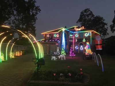
Now that you have created your first computer animated lights controller, so much is possible. When you build more Arduino controllers, they become part of your growing display. xLights makes all of your lights work as one complete show! You can created dozens of lighted decoration using white “coro” shapes, arches that bounce and glow with lights, line your house with lights, create animated trees, and more. Check out this holiday display video that was made from Arduino light controllers and xLights animation software.
You can also visit my website www.itwinkle.org for much more information on building computerized Christmas lights.
There is an online community that can help with your questions with computerized holiday lights. If you are on Facebook, join these groups to make new friends and solve problems:
- Advanced RGB and Pixels 101
- Advanced RGB Pixels and Controllers
- xLights Support Group
- Official xLights Support Group
There are also excellent online discussion forums where you can learn much more about computerized lights:
If you want to learn more about xLights, here is the manual, wiki, instructional videos, and discussion forum.
Step 26: Control Your Lights From the Internet!
Normally, your computer controls how your Christmas lights are animated. You create animations with the xLights software, then it sends commands to your light controllers and strings to animate the them.
While the convenience of having a single computer for creating animations and animating your lights is nice, leaving your computer powered on all day during the Christmas season is not that efficient. If you accidentally turn off your computer, reboot it, the computer crashes, etc., your light show stops. Powering a computer 24x7 is not efficient with electric, either.
Some people solve this problem by creating your animations using your home computer, then playing back the animations and controling your lights using a separate, low-power computer. This way you can continue to use your home computer as usual throughout the day, while the low-power computer is running 24x7, dedicated to playing your light show. The Raspberry Pi is perfect for this purpose. In xLights, you save your animations as playback files, then upload them into a special program (Falcon Player) on the Raspberry Pi that simply plays the files.
The Falcon Player software is quite powerful. With a little bit of tweaking, not only can it play animations created from xLights, but it can allow Internet control of your light show! By saving the xLights animations as multiple playback files (one animation per file, for example), people visiting a webpage can click buttons that tells Falcon Player which animation file to play. For instance, an animation can make your lights look like candy canes with red & white lights, while another animation file can make your house sparkle with twinkling lights. When no one is actively "controlling" your lights, a "regular" animation file is played for cars passing by.
The nice thing about Internet control of your Christmas lights is that is uses your existing knowledge of xLights (for creating animations). And if you are already using Falcon Player to playback the animations, you don't have to learn much new there, either! Internet control is mostly about tweaking Falcon Player to accept commands from the Internet and it's not that hard to do!
To learn more how to control your Christmas lights from the internet, click here!
Step 27: Running Your Light Controller Away From Home or Apart From Your Home Network


Some people do not want their light controller on their home network. Their Arduino light controller is too far from the router, perhaps in an outside building. Or some people prefer connecting the light controller directly to their laptop, useful for demonstrating the lights away from home.
If you wish to run your light controller without a home network, here is how to do it:
When your laptop is away from home or out of range of your network, Windows will assign a temporary IP address to it, especially when you connect an Ethernet cable from the laptop to another device, such as the Arduino network board. This temporary Windows address will be different than the Arduino’s IP address. For instance, Windows may assign “192.168.1.100” to your laptop while the Arduino’s IP address is locked in at 100.125.150.250. Because the first three sets of numbers are different in each IP address, the laptop will not “see” the Arduino.
The solution is to set the laptop’s IP address for its Ethernet port to a similar number as the Arduino. Use Windows’ “Network and Sharing Center” to do this. Instead of “Obtain IP address automatically”, set the laptop’s IP address permanently, using a similar IP address as your Arduino, with the last number changed to 251. For, for instance, if your Arduino’s IP address is 100.125.150.250, set the IP address of your laptop to 100.125.150.251. Here are instructions for how to do this. Also, be sure to set the subnet mask to 255.255.255.0.
Note: Be sure to use your Arduino’s IP address as a basis for setting your laptop’s IP address and not the address in this example! Also, do not accidentally set the IP address for your wireless network port. You only want to change the IP address on the Ethernet port.
Some laptops allow connecting a standard Ethernet cable directly to the Arduino network board. However, this method does not always work. If you use this method and your lights are behaving erratically, try using a special Ethernet “crossover” cable instead. If you still have problems, connect your computer to an Ethernet hub or switch, then connect your Arduino network board to the same switch, using two regular Ethernet cables.
Step 28: Configuring Your Router to “play Nice” With Your Light Controller

When building your Arduino light controller, it was assigned an IP address so that your computer/laptop can “see” it on your home network. This IP address is “static” in that it does not change; that way your computer/laptop always knows how to find it.
Your computer/laptop also has an IP address. When you connect your computer/laptop to your wireless network or plug an Ethernet cable in your router, the router provides an IP address. Any device on your home network, a computer, laptop, smart phone, smart TV, etc. are provided IP addresses from your router.
Your Arduino light computer does not request an IP address from the router; it’s address is locked in when you built it.
There is a small chance that the router can accidentally provide the IP address of your light controller to another device on your home network. This is because your router doesn’t know that the IP address for your light controller should be reserved. If your router provides the same IP address to another device, neither device will be able to communicate on the home network.
The simplest way to solve this problem is to limit the range of IP addresses that the router provides to other devices. For instance, if your router is configured to provide IP addresses between 100.125.150.2 and 100.124.150.254 (note the last digit changes from “2” in the first example to “254” in the second example), you can change this range within the router configuration. If your Arduino’s IP address is 100.125.150.250, for example, you can set the router’s IP address range to a maximum of 100.125.150.249. This way the 250 address is never provided to another device on your network.
To change router settings, simply open a web browser and go to the “website” with the IP address of your computer, though the last digit should be a “1”. For instance, if the IP address of your computer is 100.125.150.175, go to this address in your web browser: 100.125.150.1.
You may be prompted for a password. If you don’t know it, try a login name of “admin” with no password, or try a login name of “admin” with “password” for the password. If neither work, consult your router’s user manual to determine its default password.
In the attached photo, the place to change the IP address range is in the DHCP Settings page. Note the “Start IP Address” and “End IP Address” lines. On other brands of routers, this could also be found the “Advanced > Setup > LAN Setup” or “Connectivity > Local Network > Router Details > DHCP Server” menu. Every router is different; look for the area that lets you change the DHCP settings. Ultimately, you want to change the last three-digit number in the “End IP Address” to xxx.xxx.xxx.249.
Be sure to save your router changes when finished!
Step 29: Troubleshooting

If you are having problems getting your Arduino light controller to work for the first time, read this troubleshooting guide for help! You can also contact me at tominohio@gmail.com and I’ll help the best that I can.
When I power on the controller, the lights do not light turn on at all (no self-test where all of the lights display seven basic colors).
Possible causes:
- Your Arduino network board needs connected to your router/switch/hub. It needs to see a valid network connection before the Arduino will start its program.
- Are the lights getting power? Use a voltmeter to test the power and ground wires coming into the first bulb. It should read roughly +12V.
- Is the data wire for the lights connected to the correct pin on the Arduino? It should be pin 29. Try moving the data wire to pins 22-29, resetting the Arduino between each move (there is a reset button on the board), so determine which data pin is the “active” pin.
- Are your lights connected at the correct end? You cannot use both ends of the string of lights; only one end is the “start” or “input” end.
The self test works (I see all seven basic colors), but then the lights all turn red.
- This means that the light controller is not receiving any commands from laptop/computer. Start xLights then click the lightbulb icon on the toolbar is yellow. The red lights should turn off.
- The computer/laptop cannot “see” your light controller. Open a command prompt, then “ping” the light controller. If it does not respond:
- Check the Ethernet cable plugged into the light controller. If there are no green & yellow lights
- Try another Ethernet cable
- Make sure that your router/switch/hub is powered on
- Check the Arduino sketch for errors. Try redownloading the sketch from the website and upload a fresh one to the Arduino with minimal changes.
- Make sure that the IP address in the sketch matches the IP address that you “pinged” with.
- Compare your computer/laptop’s IP address with the IP address assigned to the light controller. The first three sets of 3-digit numbers must match. The fourth 3-digit number must be different between the computer/laptop and light controller.
- Check the Ethernet cable plugged into the light controller. If there are no green & yellow lights
The light controller goes through the seven basic colors at power up and there are no red lights (this is good). But I cannot get xLights to display anything on the lights.
- Make that the lightbulb icon on the xLights toolbar is yellow. This allows xLights to activate your lights.
- In the xLights Setup tab, verify that the “Port” is set to the IP address that was assigned to your light controller. If only using one string of lights of 50 bulbs, make sure that the “Baud Rate or E1.31 Univ” is set to “1” and that “Num Channels” is set to “150”.
- Is the data wire for the lights connected to the correct pin on the Arduino? It should be pin 29. Try moving the data wire to pins 22-29, resetting the Arduino between each move (there is a reset button on the board), so determine which data pin is the “active” pin.
I am using more than one string from this example (I am using four strings of 50 bulbs each). How do I set this up?
- Plug the data wires from each string into pins 29, 28, 27, and 26.
- In the xLights Setup tab, click “Add E1.31” to create a new Lighting Network. Use these settings:
- Method: Unicast
- IP address: (enter IP address of your light controller)
- Starting Universe #: 1
- Last Channel: 150
- Description: String 1
- Click [OK] to save your changes.
- Repeat the steps above three more times, changing the Starting Universe # to “2”, “3”, and “4” and the Description to match.
- Click [Save Setup] to save your changes.
- In the xLights Layout tab, draw four “Single line” models. Update the properties for each model to:
- First line: Nodes/String: 50, Start Channel: 1
- Second line: Nodes/String: 50, Start Channel: 151
- Third line: Nodes/String: 50, Start Channel: 301
- Fourth line: Nodes/String: 50, Start Channel: 451
- Click [Save] button to save your Layout changes
- Create a new sequence and assign some effects to your four “line” models!
Can I connect light strings together, end to end?
- For 12V lights, you can connect two strings of 50 together, end to end, making a single string of 100 lights. Make sure that you update the Arduino sketch’s MAXBULBS line in global.h to reflect the longer string, then re-upload the code to your Arduino.
- The Arduino light controller will easily support up to 200 bulbs. This can be four strings of 50 or two strings of 100. With extra work and a more complex configuration, it can support up to 400 bulbs. Please email me at tominohio@gmail.com if you are interesting in trying this.
Can strings be shorter than 50 bulbs?
- You can cut strings shorter, if you like. If you only need a string of 36 bulbs, for instance, cut off 14 bulbs at the end of the string (the “output” side). Be sure to update the number of channels in the xLights Setup tab according (36 bulbs would be 108 channels) and the number of nodes in the models in the xLights Layout tab.
My lights are animating, but there is a lot of flickering and/or incorrect colors.
- Make sure that the string is receiving a full 12V of power. Use a voltmeter to test the voltage at the first bulb in the string.
- Your string is too long (more than 100 bulbs).
- Your extension cable is too long (greater than 50-60 feet).
- You are not using custom wired Ethernet cable for your extension cable. This is important to reduce interference in the data line. Refer to the earlier steps on how to build this cable.
- If you have an Ethernet cable connecting directly from your computer/laptop to the light controller, try connecting each to a network switch/hub in the middle with two Ethernet cables.
- Inserting a 220-ohm resistor in series with the light string’s data line may fix the problem. This technique absorbs signal “bounceback” interference to other strings as it travels to the end of the string and back.
My lights animate for a while, then everything freezes. The lights on the network board are off, too.
- Make sure that the input voltage that powers the Arduino is at least 7V. 5V is not enough power and will cause the Arduino to stop working occasionally. 12V power to the Arduino can overheat and damage it.
- Instead of sharing the power supply for the lights and Arduino, use a separate 7V power supply for the Arduino. Be sure to connect a wire between both power supply ground terminals if you do this.
When I start xLights, I receive a message about some other process is using the lights.
- This can happen when you click the “xLights Scheduler” icon on the desktop instead of the regular “xLights” or “xLights 64” icon. It is a bug in the xLights pgram. You can ignore this message; it does not seem to hurt anything.
Step 30: Credits


- Thanks to my friend Keith for the sketch that turns an Arduino into a DMX light controller! But more than that, many thanks for being a friend through the years, working on Christmas lights together. I couldn't ask for a better friend!
- Thanks to the xLights development team (of which Keith is a member) for creating a free, constantly evolving/improving, flexible light animation system. And thanks to the xlights Facebook community for helping with my many questions.
- Thanks to the Schantz Makerspace in Orrville, Ohio for prototyping this light controller and working out all of the bugs. Makerspaces are a great way of bring great minds together, helping each other in community.

Participated in the
LED Contest 2017

Participated in the
Arduino Contest 2017


