

Introduction: WiFi LED Strip Controller Based on ESP-8266


I have a LED strip in my room. It's cool, but there is one small problem. Sometimes you need to exercise yourself to turn it on/off or change color, so decided to improve a controller of the strip.
I used some basic electronics (for me) and stuff to create the "Mighty Box". Here is an instruction how I made this awesome thing.
Let's begin!
Step 1: How Does It Work?


The Idea is simple.
I wrote a website (photo above) that looks exactly like original remote then connected IR LED to NodeMCU and set a server on it.
When you access the website (or just site because it is only on your local network) you can click buttons. When you click one Arduino (or in this case ESP8266) sends IR code to the original controller, just like a normal remote.
And this is the whole philosophy of this thing.
Let's create it!
Step 2: What Do You Need?


Here is a small list of things I used.
- ESP8266 - I used NodeMCU (same MCU but easier to program)
- 12v to 5v Step-Down conventer (cheap USB car charger works really well)
- IR diode - to send IR codes (like original remote)
- DC Jack and DC socket (which fits between power supply from strip and controller)
- box - I used one after bigger TicTac's
- of course, I used RGB LED strip with controller
Step 3: Test the IR Diode and Library


I programmed everything in Arduino IDE. It needs some adaptations. I'll not write them here. You can find them on the Internet e.g here
I tested the original IR remote library (default in Arduino environment) and now I know (as I expected) that it doesn't work. I've found a version prepared for ESP8266. You have to download the library and install in Arduino IDE.
Download the IRremoteESP8266 library.
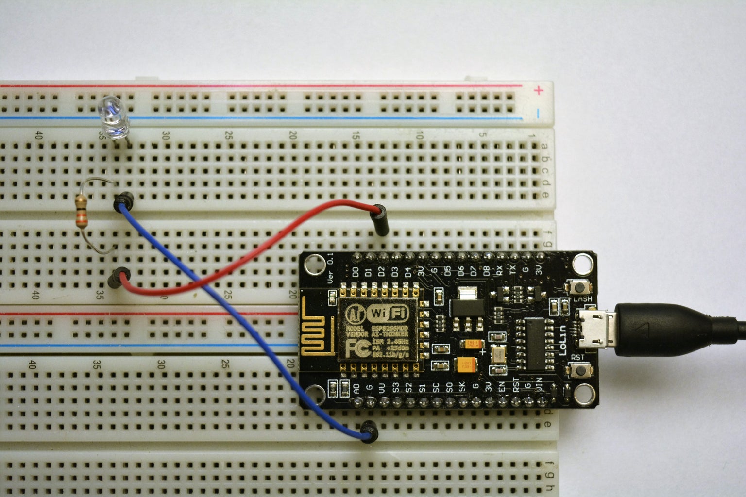
In this step also connect and test your IR diode. In a gallery, there's a schematic. Basing on it connect IR LED, then upload following Sketch and point the IR LED to the controller. The LED strip should blink (turns on and off).
Step 4: Upload Sketch
Upload following Sketch to NodeMCU.
Change SSID of your WiFi in line 26 and password in 27.
In line 29 You can change IP adress, 30 - gateway, 30 - network mask (in case you need)
No more configuration is needed.
Step 5: Make Power System!


First I took apart car USB charger. I separated PCB board, found GND, 5V, 12V. Then I made "extension" cable for LED's power supply because I needed to get 12V from the power supply. I connected 12V and GND to PCB board. Then 5V and GND from charger connected to NodeMCU.
Check a schematic above ;)
Step 6: Time for Enclosure


I searched for appropriate enclosure in local stores, but I failed. I decided to use big TicTac box.
I took off all labels by holding box above kettle. A steam melted glue and it was really easy to peel off labels.
Then I drilled one hole on the bottom of the box. It is not circular at all. It has one distortion coming to a corner of the box. I made it for power cable outcoming from the box.
Ther's also another hole. It is on the top (I mean closing) of the box. It's for IR LED's cable.
Step 7: Put Everything Together


- Drag DC jack through the bottom hole, from inside of a box to outside.
- Place DC socket (from inside of the box) in the bottom hole, then screw it using a nut.
- Isolate PCB board e.g. using tape.
- Insert NodeMCU to the box.
- Drag the IR's cable through the hole in closing.
- Add some plastic material between a wall of the box and NodeMCU, to prevent it from moving.
- Add some LED frame/holder into top hole to make it look better and prevent the cable from moving.
Step 8: Use It!

Connect the power supply to "Mighty box" and point IR LED to the controller.
Type 192.168.1.111 (or another in case you changed it). You can also access this device through link http://led.local
Have fun!
Show me your implementations of this project ;)


