

Introduction: Capers II, a Hexapod Robot


This Instructable will show you how to build your very own hexapod robot, I call the design Capers II.
Robot Design
A hexapod robot is a robot with six legs. Each leg is actuated by three servos: one for forward/backward movement, one for up/down movement, and one to bend the leg in the middle. This gives the robot three degrees of freedom, allowing it to move in any direction.
Some hexapod robots are symmetrically designed, with the six legs equally spaced around a linearly symmetrical body. Capers II, on the other hand, has a slightly elongated body, giving the robot a more natural appearance and the ability to use gaits reminiscent of insects.
Motion
A six-legged robot has a great deal of flexibility in the ways it is able to move. Capers II is able to use several different gait patterns while walking.
The code that powers Capers II also allows for two modes in which the legs stay planted on the ground, but the body is allowed to move through its entire range of motion.
Robot Control
Capers II features wireless control using a Playstation 2 controller.

Source
All of the code, design files, descriptions, and other utilities needed to build, calibrate, and run the Capers II hexapod can be found in a GitHub repository for the project.

Step 1: Gather Your Parts


You will need the parts below to build your hexapod robot.
Electronic Components
1 x Botboarduino
Arduino-compatible robot controller
1 x SSC-32U Servo Controller
USB servo control board
1 x NiMH Battery Charger
Charger for NiMH battery charger
1 x NiMH Battery Pack
6V 2800mAh NiMH batter
1 x Wiring Harness
Battery wiring harness with switch
1 x PS2 Controller/Receiver
Wireless PS2 controller with receiver breakout
18 x Hitec HS-645MG*
High-torque analog servo
Hardware
36 x M2.2 x 5mm thread-forming screws
For attaching the servo horns
54 x M3 Nut
To put on the M3 screws
72 x 4-40 x 0.375" Screws
For attaching the servos
72 x 4-40 Nuts
To put on the 4-40 screws
6 x 3mm bore, 8mm OD Flanged Ball Bearings
These are used for the coxa joint
60 x M3 x 5mm Cap Screws
For connecting the servo brackets together
6 x M3 x 8mm Countersunk Screws
Used with the ball bearings
6 x M3 x 50mm Standoffs
These hold the top and bottom body plates together
Frame
Hexapod frames are actually fairly easy to obtain. A simple search should yield several different sellers on different platforms. I purchased my frame on eBay.
* It may be tempting to go with less expensive servos than the Hitec HS-645MGs used in this Instructable. However, I would highly recommend getting the name brand. The robot requires quite a bit of strength from its servos in order to work correctly.
Project Cost
The total cost at current prices is detailed in the table below.
| Part | Quantity | Unit Cost | Total Cost |
|---|---|---|---|
| Hitec HS-645MG Servos | 18 | $28.99 | $521.82 |
| Botboarduino | 1 | $34.99 | $34.99 |
| SSC-32 Servo Driver | 1 | $44.95 | $44.99 |
| Wireless PS2 Controller | 1 | $23.85 | $23.85 |
| 6V 2800mAh Battery | 1 | $26.95 | $26.95 |
| Battery Charger | 1 | $21.95 | $21.95 |
| Frame | 1 | ~$80.00 | ~$80.00 |
| Power Switch | 1 | $4.95 | $4.95 |
| Total | $759.46 | ||
Step 2: Anatomy of a Hexapod

Before we get to actually building the hexapod, it will be useful to establish a naming convention for the different parts of the robot. The robot has three segments on each of its six legs and three servos for the joints between the leg parts. The naming scheme we will use for the different parts of the legs will be analogous to the arthropod leg.
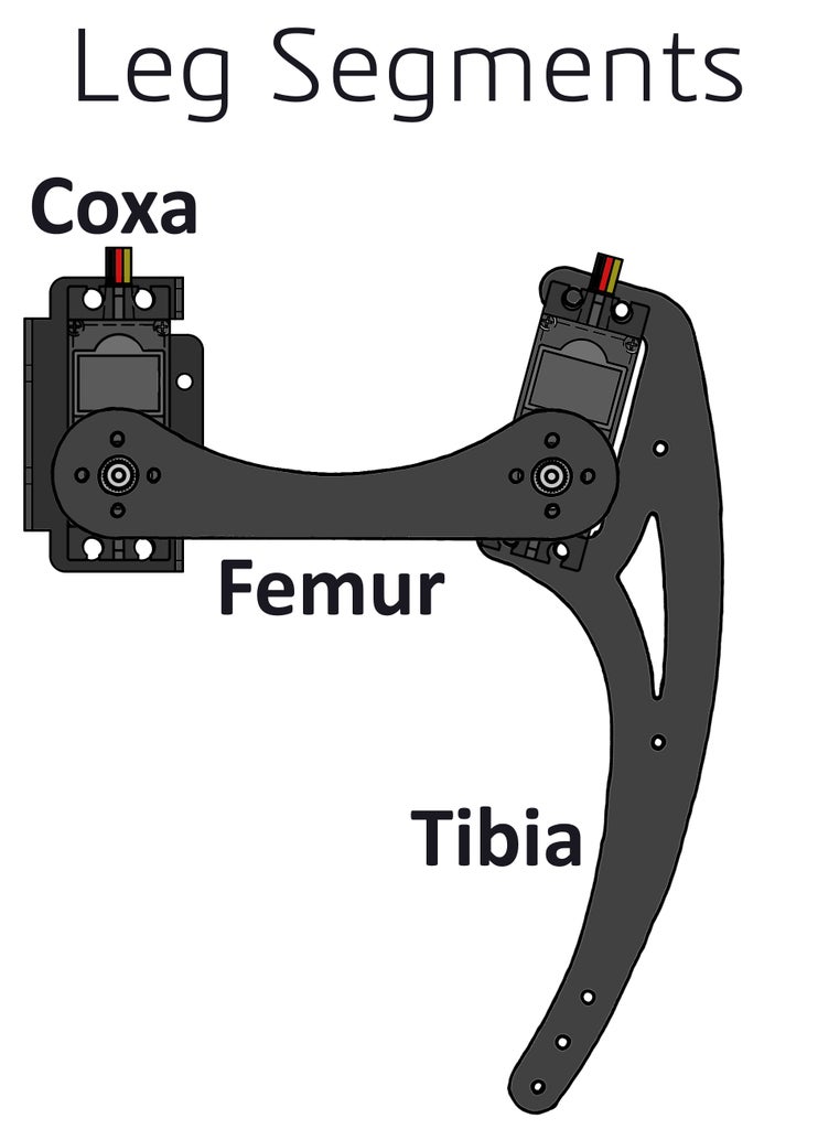
The leg segment closest to the body will be called the coxa. In our build, the coxa is a servo bracket assembly we will start building in the next step. The second leg segment is the femur. The third leg segment, the last one on each leg, is the tibia.
The servos will be named according to the leg segment they move. The servo that attaches to the body of the hexapod is the coxa servo. The servo that lifts and lowers each leg is the femur servo. The servo that allows the legs to bend in the middle is the tibia servo.
Step 3: Build the Servo Bracket Assemblies


It's time to start building. The first parts of the Capers II hexapod we will put together are the servo bracket assemblies that will go on the base of each leg. We will build the servo bracket assemblies in pairs because, like many parts of the hexapod, we will have three bracket assemblies on the left side of the robot, and three on the right. We will need to build our sub-assemblies in pairs that are mirror images of each other.
One other important detail to keep in mind while attaching the ball bearings to the servo brackets is that you do not want to tighten the screw so much that the ball bearing can no longer move. Keep the nut on the back side of the bracket slightly loose so that the ball bearing can spin freely. This is one reason to use thread locking compound on this nut, so that you can leave it a bit loose and still not worry about the nut falling off.
Step 4: Attach Servos to the Bracket Assemblies


With the servo brackets built into pairs of mirrored joints, we can now attach the servos themselves to the brackets. The orientation of the servos is not as difficult to figure out as the orientation of the brackets, but it can still be a touch confusing.
The first servo attaches to the bracket with the ball bearing. This servo should be oriented so that the motor shaft aligns with the ball bearing. The second servo should be mounted with the motor shaft on the side closest to the ball bearing. Attach the servos to the brackets using four 4-40 x 0.375" screws and 4-40 nuts for each servo. It is advisable to use some thread lock on the screws so vibrations from the robot do not loosen the servos.
Step 5: Attach Servos to the Tibias


Mounting servos to the tibia parts is a simple task. First, this is another step involving assembling parts in mirrored pairs. We need three tibias for the right side of the robot, and three more for the left. Start by arranging your tibia pieces in opposing directions so it is easier to keep track of which you've already assembled.
Attach the servos to the tibia parts with the motor shaft closer to the pointy end of each tibia. Like the coxa and femur servos we assembled in the previous step, the tibia servos connect using four 4-40 x 0.375" screws and 4-40 nuts each.
Step 6: Attach Servo Horns to the Femurs


Next we need to connect the servo horns to the femur so that, after the next step, we can assemble the legs. The Hitec HS-645MG servos actually come with a few different horns in the box. The ones we will use on the Capers II robot are the white circular horns that may have come pre-installed on your motors.
Each of the femur parts needs two servo horns. Unlike every other part of the robot, we do not need to worry about building the femurs in mirrored pairs because they are symmetrical anyway.
Attach a servo horn onto each side of each femur using four M2.2 thread-forming screws on each servo horn.
Step 7: Center the Servos

In order for the code running on the Botboarduino to control Capers II, it is critically important that the controller knows the orientation of each leg when the servos are centered. The code assumes that, when all the servos are centered, the coxa faces directly away from the body, the femur is level with the ground, and the tibia is at an angle of 75 degrees relative to the femur. In order to guarantee this position, we need to make sure all the servos are centered before assembling the legs, which we will do in the next step.
We will use the Botboarduino to center the servos. The GitHub repository for this project contains a simple sketch called servo_center.
- Open the servo_center sketch in the Arduino IDE
- From the Tools menu, change the board type to "Arduino Duemilanove or Diecimila"
- Upload the code to the Botboarduino via USB
Then, once the sketch is running on the Botboarduino, simply plug each servo into the servo header on pin 2.
Step 8: Assemble the Legs


With the coxa joint, the femur, and the tibia individually assembled, they can all be put together to create the robot's legs. At this point, all of the servos should be in their center position. Connecting the leg parts together in the correct orientation is integral to the correct operation of the hexapod.
The first step is attaching the femurs to the femur servo/coxa joint. The femur attaches to the femur servo so that the femur itself is perpendicular to the servo. One side of the femur is flat, and the other side is curved. The flat side faces down, which is the side closest to the ball bearing on the coxa joint. Press the servo horn on the femur onto the motor shaft and secure it in place using one of the screws included with the servo.
The second step is to attach the tibia to the femur. Start by lining up the tibia so that it is perpendicular the femur. Then, rotate the tibia towards the coxa joint slightly. As you rotate the part, you will feel the teeth on the motor shaft engaging with the teeth on the servo horn. Rotate the tibia in until you feel the part "click" into place in its next position, which is 15 degrees from perpendicular.

Step 9: Attach Servo Horns and Standoffs to the Upper Chassis


Now that the legs are all fully assembled, we will set them aside briefly while we turn our attention to the hexapod's chassis. In this step, we will accomplish two related tasks before we start working on the electronics.
First, six servo horns will mount onto the upper chassis piece in the same way the servo horns were mounted onto the femurs. Using a pair of M2.2 x 5mm thread-forming screws, attach six servo horns to the part.
Second we will attach the six M3 x 50mm screws to the upper chassis piece in preparation for mounting the lower chassis towards the end of this Instructable. There will be one standoff mounted near each of the legs.
Step 10: Upload Capers II Sketch to the Botboarduino

The Capers II hexapod is designed so that the USB port on the Botboarduino will be accessible even after the robot is fully assembled. This allows the robot to be reprogrammed without any disassembly. However, since the Botboarduino is, at this point, not yet caged inside the robot chassis, we will program the board now and take advantage of the convenience.
There is one preparatory step needed to program the Botboarduino. There are a number of jumpers on the board, and we will take a closer look at those in the next step, but for now, find the solder jumper labeled USB/ext. This jumper is used to select the power source for the board. Ultimately we will power the board from an external source, but for now, move the jumper to the USB position.
With the jumper set, head over to the GitHub repository for this project and download the code. Then, open Capers_II_PS2_SSC32.ino in the Arduino IDE. Uploading the sketch to the Botboarduino will follow the same process we used earlier when centering the servos:
- Open the servo_center sketch in the Arduino IDE
- From the Tools menu, change the board type to "Arduino Duemilanove or Diecimila"
- Upload the code to the Botboarduino via USB
Uploading the sketch may take a little longer than your typical Arduino program. The Capers II code is quite large for an Arduino, taking up about 75% of the Botboarduino's memory.
Step 11: Set Botboarduino and SSC-32 Jumpers


Another step we will perform prior to mounting the electronics inside the Capers II chassis, because the electronics become much less accessible once inside the robot's body, is configuring a series of jumpers on the Botboarduino and SSC-32 servo controller. Each board has several jumpers used to select various settings. Many of these jumpers configure power delivery options for the board and it is therefore vitally important that they are set correctly.
Botboarduino Jumpers
The Botboarduino has a total of 13 jumpers placed around the board. First we have two jumpers near the screw terminal. We've actually already played with the first jumper, the one used to select the power source for the Botboarduino, between USB and external power. For programming the Botboarduino we need to power the board via USB. However, the board will be powered by a battery in the robot, so we will switch this jumper to the ext setting.

The jumper next to the power source selection is labeled VS=VL. There are two ways the Botboarduino can be powered: first, separate power sources can be used to power the logic components of the board and the servo connectors, second, both systems can be powered from the same source. Since we will not be connecting servos directly to the Botboarduino, they connect to the SSC-32 instead, we will use a single power source for the entire system. Therefore, install a jumper onto the VS=VL pins.

Next, moving across the board a little bit, there is a jumper near the speaker. This jumper simply enables or disables the speaker. This option is your choice. Install the jumper to enable the speaker, or remove it and the speaker will be disabled.
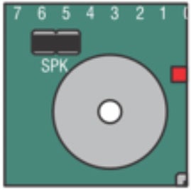
Moving further across the board, you will find a group of four jumpers near the buttons and LEDs on the Botboarduino. These jumpers will not really do anything in the Capers II hexapod. They enable or disable the buttons, but we will not be using the buttons anyway. Just leave these jumpers installed.

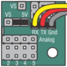
Next, there are three jumpers next to three banks of pins on the side of the Botboarduino opposite the screw terminal. These jumpers, control the voltage delivered to those banks of pins between the VS voltage supplied to the screw terminal and 5V. We will be using those blocks of pins to connect the PS2 controller, and connect to the SSC-32. Therefore, make sure all three of these jumpers are set to 5V.

The jumper underneath the blocks of pins is labeled similarly to those next to the blocks of pins above. This jumper controls the same power deliver option for the TX/RX pins. Set this jumper to 5V as well.
SSC-32 Jumpers
The SSC-32 servo controller has far fewer jumpers to configure. It only has two. On one side of the screw terminal there is a jumper labeled VS=VL. This jumper has the same function as the same-labeled jumper on the Botboarduino. Since we will power the SSC-32 from a single power source (the battery), we will install a jumper on these pins.
These second jumper is found on the opposite side of the screw terminal. It is actually a set of four pins that control the same setting. It is possible to use two different power sources for servos on the left and right side of the SSC-32. We will be using a single battery, so install two jumpers across the pins labeled, VS1 VS2.
Step 12: Mount the Botboarduino Onto the Upper Chassis


Getting all of the electronics and wiring to fit inside the robot's chassis is a little bit tricky. We will be building a kind of stack of boards inside the robot's frame. All of the boards will hang upside-down from the upper chassis plate when the robot stands.
The first step to assembling the electronics package is mounting the Botboarduino onto the upper chassis plate. Start by installing four 6mm nylon standoffs onto the holes in the upper chassis plate that line up with the mounting holes on the Botboarduino (you may need to add some holes like I did). Then place the Botboarduino onto the standoffs.
Step 13: Install the Controller Receiver


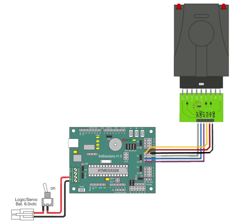
The next component to be added to the electronics stack is the controller. Before actually mounting the controller on top of the Botboarduino, we need to connect the receiver electronically - and we will also be adding a few other electrical connections as well.
Connect the Controller Receiver
The controller receiver comes with a set of pin-terminated wires in the box. There are six connections on the receiver. On the Botboarduino, the receiver connects to the 6-9 block of pins:
- Receiver GND to Botboarduino pin 9 GND
- Receiver 5V to Botboarduino pin 9 5V
- Receiver CLK to Botboarduino pin 9
- Receiver ATT to Botboarduino pin 8
- Receiver CMD to Botboarduino pin 7
- Receiver DAT to Botboarduino pin 6
With the electrical connections made, we can mount the controller receive on top of the Botboarduino. First, add a nylon nut on top of the two nylon standoffs on the side of the Botboarduino with the screw terminal. On top of these nuts, add two [add length]mm nylon standoffs. On the side of the Botboarduino opposite the screw terminal, add two [add length]mm nylon standoffs. Place the controller receiver on the two standoffs on the screw terminal side of the Botboarduino. The receiver should fit snugly into place with the end of the receive itself nestled next to the wires we've already plugged in.
Add Other Connections
Since we will be installing the controller receiver and the SSC-32 on top of the Botboarduino in the next few steps, the Botboarduino will soon be inaccessible. Therefore, it will be difficult later on to make the other connections between the Botboarduino and the other parts of the system. We will install a few other wires to the Botboarduino now, before mounting the controller receiver. Those wires will connect to other parts of the system later on.
First, we will add the wires we will use later to connect the Botboarduino to the SSC-32. Three wires are used for this. First, a black wire connects to the GND on pin 13. Next, connect a yellow cable to the signal on pin 13. Finally, connect a red wire to the signal on pin 12. For now, these wires will just dangle free until we install the SSC-32.
The final connection to make is the one that will deliver power to the Botboarduino later on. The battery will connect directly to the SSC-32 and then the power will chain to the Botboarduino. There are two power connections on the Botboarduino screw terminal. As a preparatory step, connect a + and - wire to the screw terminal labeled VL.
Step 14: Set the SSC-32U Baud Rate
In a moment we will add the SSC-32U servo controller to the electronics stack inside the hexapod. First, however, we need to take the preparatory step of setting the baud rate on the SSC-32U. The default baud rate of the SSC-32U is 9600, however, the Capers II code we will be running on the Botboarduino uses a baud rate of 38400, allowing significantly faster communication between the Botboarduino and the SSC-32U.
In order to set the SSC-32U baud rate, we will need to power on the board. To do this, simply plug your SSC-32U into an available USB port on your computer. Then, on the SSC-32U, you will find a button labeled "baud." Next to that button, there are two LEDs, one labeled "A" and one labeled "B."
Press and hold the baud button. At first, the LEDs illuminate to indicate the current baud rate setting. The default of 9600 is indicated by a green LED. After two seconds, the LEDs will start to alternate, indicating that you can now set a new baud rate. Release the button. Then, press the button to cycle through the baud rate settings:
- 9600 - green
- 38400-red
- 115200-red and green
So, cycle through the LEDs until a red LED illuminates. Once the correct baud rate is selected, do nothing. After five seconds, the new baud rate will be saved to the board's memory.
Step 15: Add the SSC-32 Servo Controller


Our stack of electronics will be topped off by the SSC-32 servo controller. The SSC-32 simply mounts on top of the standoffs added to the stack on top of the controller receiver. Orient the SSSC-32 so that the screw terminal on the SSC-32 is on top of the screw terminal on the Botboarduino, because we will be connecting these screw terminals together. Fasten the SSC-32 in place using four nylon nuts.
With the SSC-32 in place, we will make a few connections using the wires we installed on the Botboarduino earlier. First, power from the battery will be connected directly to the SSC-32 - we will do this in the next step. Then, the SSC-32 delivers power to the Botboarduino. We already have wires installed on the VL screw terminal on the Botboarduino. Attach the other end of this wire to the VL screw terminals on the SSC-32.
Next we need to connect the Botboarduino and the SSC-32 together so that they can communicate with each other. We already have three wires installed on the Botboarduino. These wires connect to the RX/TX/GND pins in the middle of the SSC-32.

Step 16: Attach the Power Switch


At this point, we've completed the electronics stack at the heart of the robot. In this step we will add the power switch and wiring harness that will deliver power from the battery to the electronics system. There is a hole in the upper chassis plate on the side of the electronics stack opposite the screw terminals. Start by removing the washers from the button and then install the button into this hole. If you take a look at the large flat washer included with the switch, you will notice a tab on one side of the washer. This tab will insert into one of the smaller holes next to the one in which the switch is installed. This washer keeps the switch oriented correctly. With the washer in place, fasten the switch in place using the included nut.
With the switch installed, it can be wired into the system. The switch has a battery connector on one side, and a pair of wires on the opposite side. These wires connect to the VS1 screw terminals on the SSC-32. Remember that we've already set our jumpers to connect VS1 to VS2, allowing the battery to power all the servos, and connect VS1 to VL, allowing the battery to power the board logic as well. The wire connecting VL on the SSC-32 to VL on the Botboarduino delivers power to the Botboarduino logic.
Step 17: Attach Legs to the Body


Alright, we are now in the final stretch of the build process for our hexapod robot. In this step we will attach all of the previously-assembled legs to the upper chassis plate (the one to which we attached all the electronics). When attaching the coxa servos on the legs to the servo horns on the upper chassis plate, the servos must be oriented so that the leg faces directly away from the center point of the robot. As we discussed when assembling the legs, in order for the robot firmware to operate correctly, the robot must be assembled so that when the servos are centered, the robot is in a predetermined posture.
So, attach all six legs to the upper chassis plate. Secure the servos using the screws included with the servos. Be careful when picking up and moving the robot at this point because we have the entire leg assembly supported at a single point by the plastic servo horns.
Step 18: Attach Servos to the SSC-32


All 18 servos on the hexapod connect to the SSC-32 servo controller. The Botboarduino then issues commands to the SSC-32 to move the servos to angles calculated by the inverse kinematics algorithms that constitute the bulk of the Capers II code.
The SSC-32 has a row of servo connectors on each side of the board. These servo connections are grouped in blocks of four rows each. Each leg connects to a different block. The pin numbers for the servo connections are defined in the code.
There is one tricky aspect to connecting the legs. In order to actually make the connections, you need to turn the robot upside-down. This means, that when you are looking at the robot from the side with the switch closest to you, the right servos will actually be on the left side of the robot.
Each row of connectors has three pins: ground, signal, and 5V. Connect the servo cables with the black ground wires towards the outside of the board.
/// SSC-32 PIN NUMBERS ///
#define cRRCoxaPin 0 //Rear Right leg Hip Coxa
#define cRRFemurPin 1 //Rear Right leg Hip Femur
#define cRRTibiaPin 2 //Rear Right leg Tibia
#define cRMCoxaPin 4 //Middle Right leg Hip Coxa
#define cRMFemurPin 5 //Middle Right leg Hip Femur
#define cRMTibiaPin 6 //Middle Right leg Tibia
#define cRFCoxaPin 8 //Front Right leg Hip Coxa
#define cRFFemurPin 9 //Front Right leg Hip Femur
#define cRFTibiaPin 10 //Front Right leg Tibia
#define cLRCoxaPin 16 //Rear Left leg Hip Coxa
#define cLRFemurPin 17 //Rear Left leg Hip Femur
#define cLRTibiaPin 18 //Rear Left leg Tibia
#define cLMCoxaPin 20 //Middle Left leg Hip Coxa
#define cLMFemurPin 21 //Middle Left leg Hip Femur
#define cLMTibiaPin 22 //Middle Left leg Tibia
#define cLFCoxaPin 24 //Front Left leg Hip Coxa
#define cLFFemurPin 25 //Front Left leg Hip Femur
#define cLFTibiaPin 26 //Front Left leg Tibia
Step 19: Manage Your Cables


Right now you robot probably looks like a crazy spaghetti bowl of wires. In order for the bottom chassis plate to fit onto the hexapod, we will need to fasten down all of the servo wires so that they fit nicely underneath the brass standoffs. This step is more art than science. Just try to bundle together the wires and fit them into any crack or empty space around the SSC-32U.
The one consideration here is that the legs still have enough slack to operate on their full range of motion after fastening down the wires.
Step 20: Attach the Lower Chassis Plate


The final parts we have to install on the Capers II hexapod robot are the lower chassis plate and the battery. First of all, we need to attach the battery to the lower chassis plate. When the robot stands, the battery will hang under its body.
Place the battery in the middle of the lower chassis plate and, using two zip-ties, secure the battery in place. In order to help the robot balance, try to center the battery as precisely as possible.
With the battery mounted onto the lower chassis plate, place the assembly on top of the robot, which should still be upside down at this point, line up the ball bearings on all six legs with the holes in the lower chassis plate. This might be a little bit tricky to do. The lower chassis plate should be oriented so that the battery cable is on the opposite side of the robot from the switch cable. Finally, secure the lower chassis plate in place using six M3 x 8mm screws into the standoffs.
Step 21: Adjust Servos

Earlier, when we were assembling the legs and attaching the legs to the body, we discussed that the Capers II code expects the robot to be in a particular posture when all of the servos are centered. The femurs should be at right angles to the coxa servos. The tibias should face 15 degrees inward relative to the femurs. The legs should face directly away from the center of the robot. However, even if you were very careful while assembling the robot, when the robot turns on, you might find that the initial angles of the servos are somewhat off.
There is a utility in the Capers II code that allows you to adjust the initial servo angles of all 18 servos in order to correct any small errors in alignment introduced during assembly.
To use servo offset mode, first plug the Botboarduino into your computer via USB. The USB cord can reach the port on the Botboarduino through the front two legs. With the robot connected to your computer, turn on the switch and open Serial Monitor in the Arduino IDE. When the robot starts, you will be presented with some instructions in Serial Monitor. To enter servo offset mode, send "O" to the hexapod.
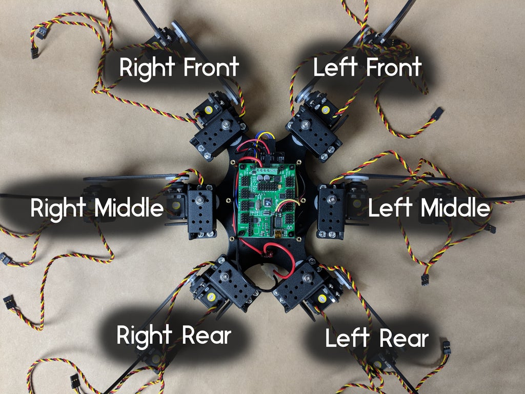
Once servo offset mode starts, you will again be presented with some options. The first step is selecting a leg. All six legs are designed by a number in the code:
- Rear Right
- Middle Right
- Front Right
- Rear Left
- Middle Left
- Front Left

To select a leg, send the leg number, along with servo designator over Serial. You can specify the coxa servo with "C," the femur servo with "B," or the tibia servo with "C." Once you have a leg selected, send "+" or "-" over Serial to increase or decrease the servo zero position.
Once you've configured all your servos, send "$" over Serial to exit servo offset mode. A prompt will ask you if you want to save your configuration. Respond "Y" to save your offsets.
Step 22: Bring Your Hexapod to Life


It has probably taken quite a bit of time, but your hexapod is now complete! All that remains to do is turn on the robot, and the controller, and take Capers II for a walk. It will be useful, of course, to know how to control the hexapod. On the PS2 controller, you have access to a set of "common controls" which are almost always active, whatever mode the robot is currently in.
The Capers II code provides several different control modes. The default mode, which is the one entered after turning the hexapod on with the Start button is walking mode. In walking mode, you will use many of the common controls to change the gait, body height, gait length, gait speed, and other movements. Steering the robot works much like FPS games. The left stick handles translation. If you used only the left stick, the robot would move around but it would always face the same direction. The right stick turns the robot.

One of the other commonly used modes is single leg control mode. As the name implies, this mode allows individual control over the legs. You can also have the robot hold its legs in a position you set.

In the final two modes, the robot does not move around the room. Rather, it will keep its feet planted and move only its body. The first of these stationary modes is shift mode. In shift mode, Capers II will keep its body level, and the sticks move the body around: forward, backward, left, right, up, and down.
The other stationary mode is rotate mode. In rotate mode, the robot's feet are still planted, and the body does perform transnational movement, rather, the body is allowed to roll, pitch, and yaw.

Runner Up in the
Epilog Challenge 9


