

Introduction: How to Make a Signal Generator| Learn to Generate Electrical Signals
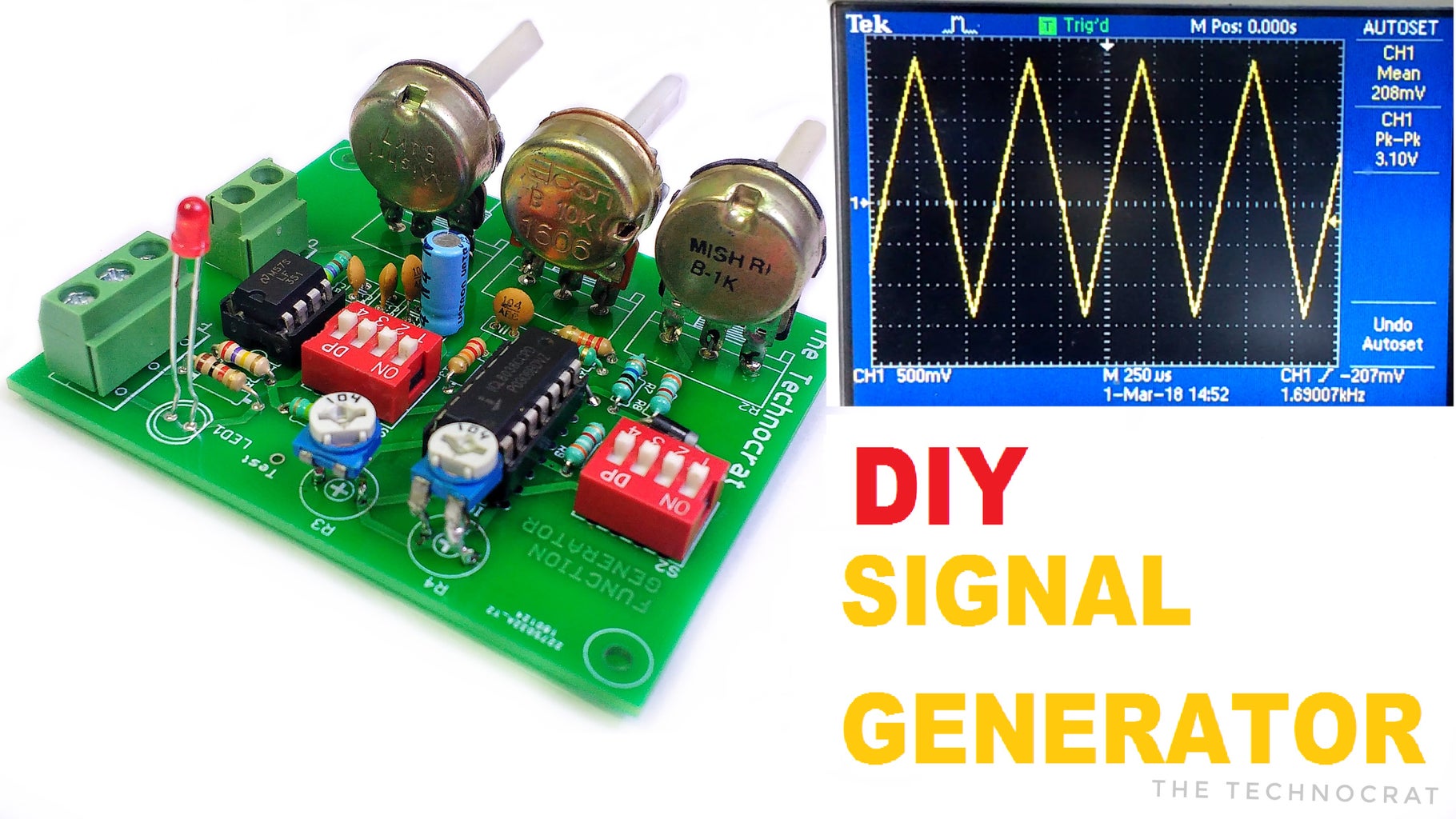


A Function generator , often known as Wave-form generator is a circuit that produces a variety of different wave-forms at a desired frequency.
Function generator is one of the important devices in laboratory when it comes to generating electrical waveforms like sine, triangle,square or pulses over a range of frequencies, amplitude and duty cyle.
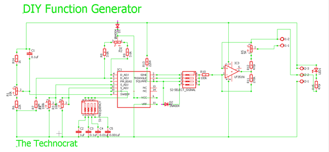
Lets learn how to build a crude signal generator with variable frequency, amplitude and duty cycle. This circuit is built around the waveform function generator IC 8038 capable of generating frequencies up to 300 KHz. My circuit is designed to generate signals up to 100 Kilo-hertz.Lets learn how to build a crude signal generator with variable frequency, amplitude and duty cycle. This circuit is built around the waveform function generator IC 8038 capable of generating frequencies up to 300 KHz. My circuit is designed to generate signals up to 100 Kilo-hertz.
It can be used to generate test signals for audio amplifiers, PWM signals for MOSFET or transistor circuits,generate clock signals for digital circuits,and this list goes on....
In this instructable lets build one on our own.
Watch this video for better understanding.
Step 1: Materials and Components You Will Need!


Here are the list of materials required to build the very crude but effective signal generator.
IC8038 signal generator IC
IC LF351 op-amp IC
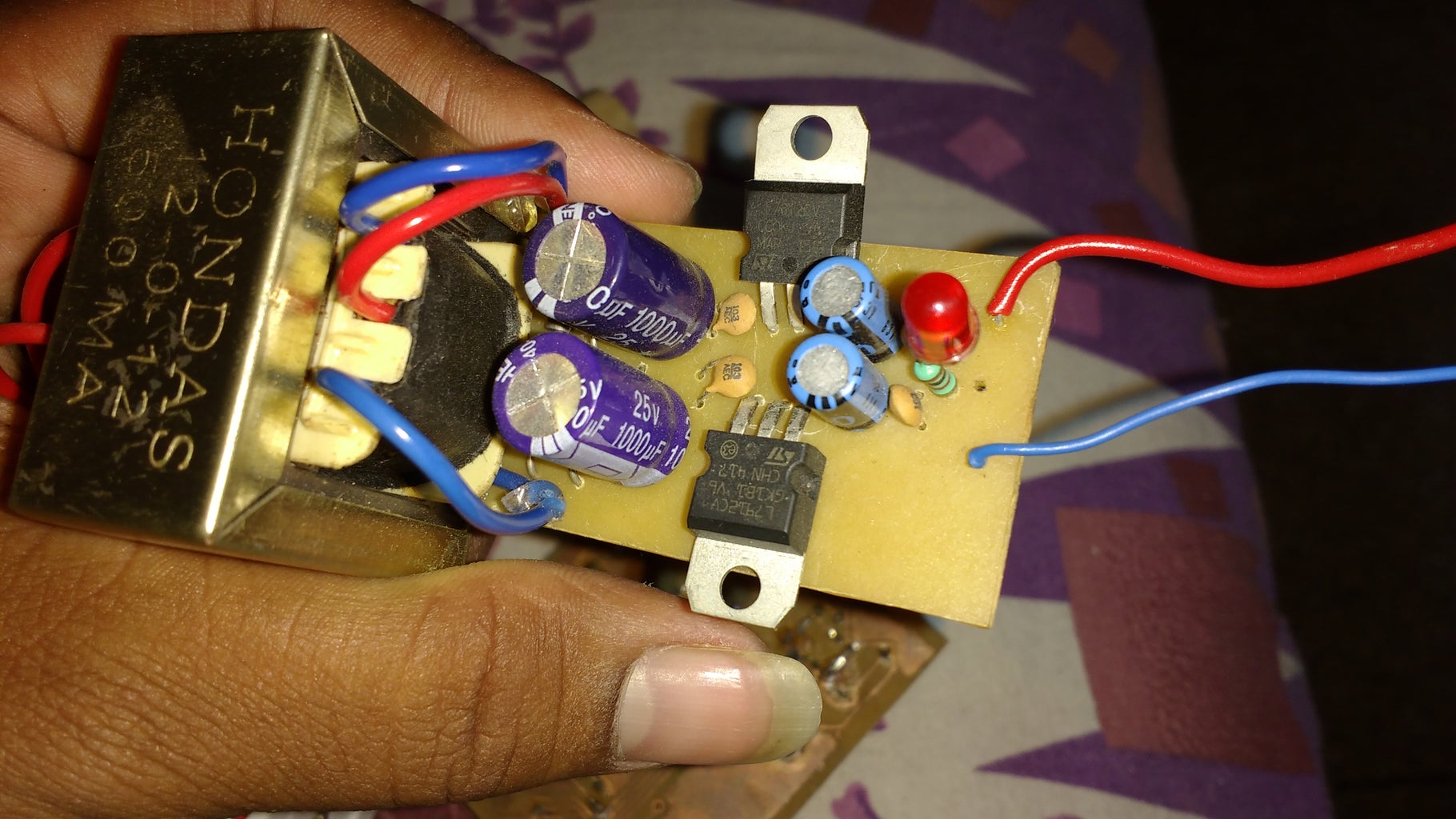
+/- 12v Dual power supply
DIP Switch 4-way
100 kOhm preset
1KOhm Pot
10 KOhm Pot
5 KOhm Pot
Capacitors-
- 1uF
- 0.1uF
- 0.01uF
- 0.001uF
Resistors-
- 1k
- 22k
- 3.6k
- 100k
- 270k
- 470r
- 10MegaOhm
IC Base Socket
Soldering Kit
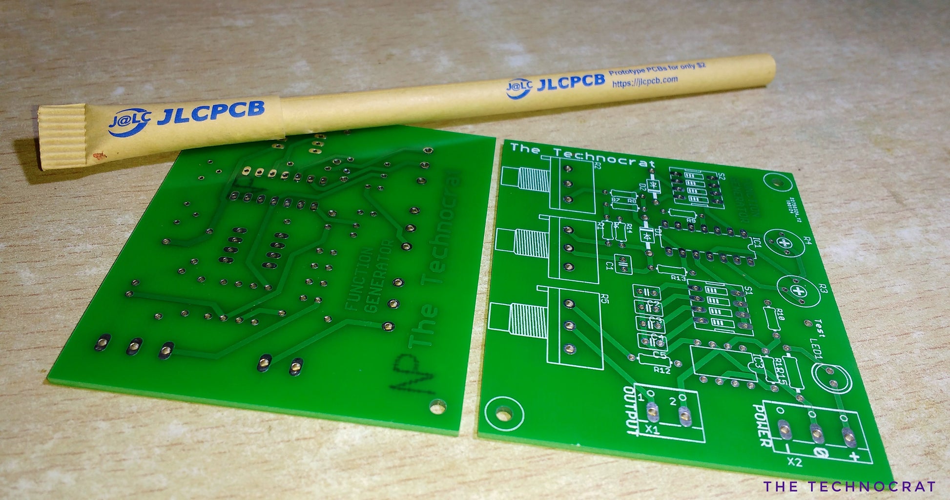
PCB (I ordered online)
The Circuit design, gerber files, PCB layout are included at the end of this instructables.
Step 2: The Theory!
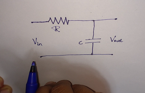


This function generator uses the Passive components like resistors and capacitors to generate a analog signal.
This circuit is built around the IC 8038 with the very minimum external components and is capable of producing the signals of frequency up-to 300KHz. You can generate Sine wave, triangle wave and square wave with this IC.
The RC oscillator is used and the output frequency is given 1 divided by 2*pi*R*C.
Therefore by varying R and C values we can vary the output frequency of the Signal generator. Hence a precisely calculated values of fixed value ceramic capacitors are used, which act as frequency multiplier and the variable resistor acts as the frequency fine tune adjustment ( Here in this circuit: 10Kohm Pot).
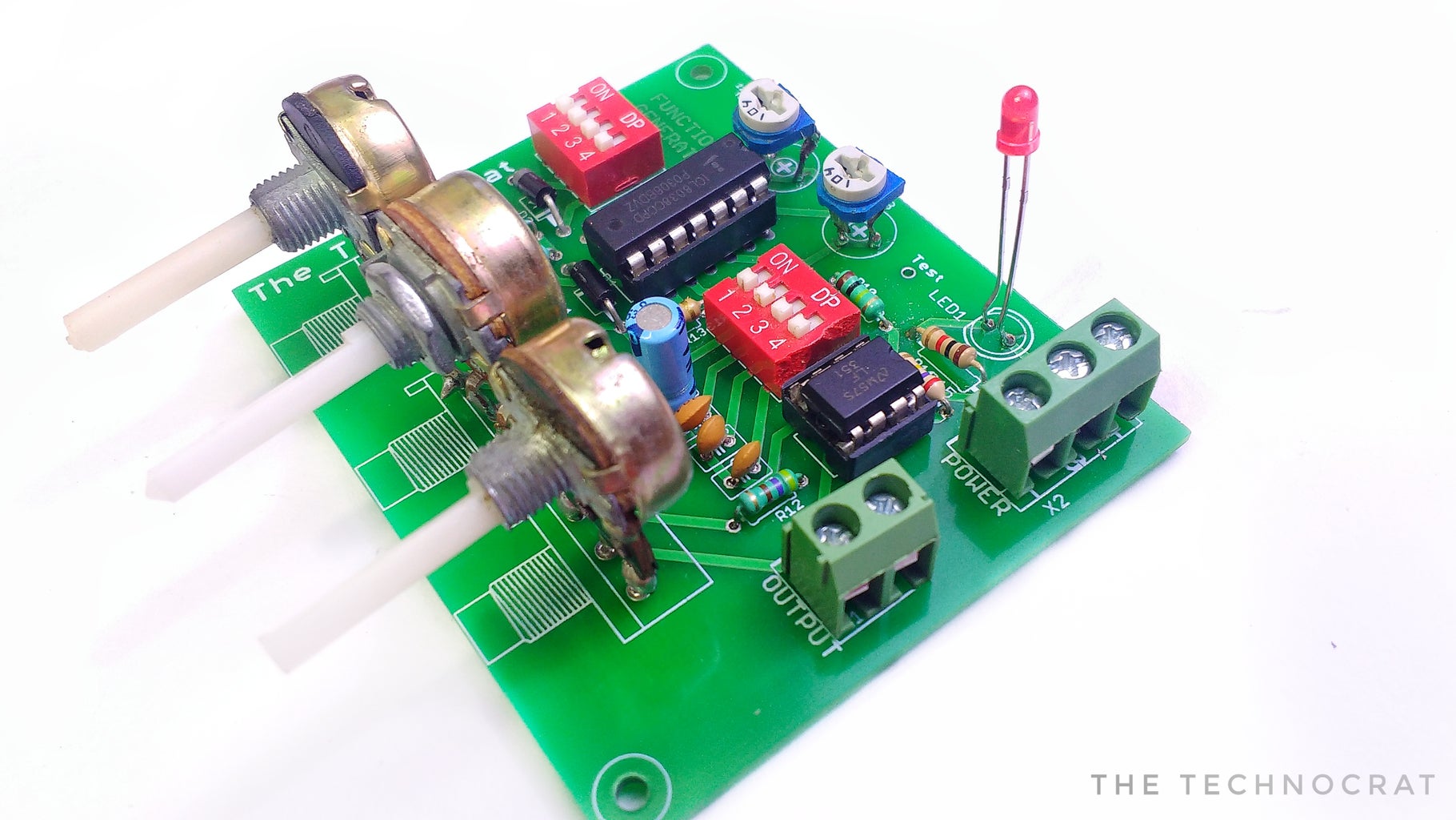
Step 3: Soldering Time!


Once you gathered all the components, Solder them on to the PCB using your soldering Kit. Use a little bit of flux for perfect soldering.
Refer the circuit diagram and the silkscreen on the PCB to place the components first. Flip it over and start to solder each pads one by one.
If you don't want to buy a ready made PCB you can assemble the components on a piece of Pref-board. Or you can even Manufacture your PCB at home. That is actually real fun!!! Please watch my video on that too.
I will attach the Eagle Schematic files and Gerber files. You can use the Gerber files to order PCB online if you want to.
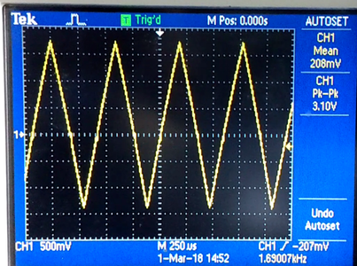
Step 4: Testing the Circuit

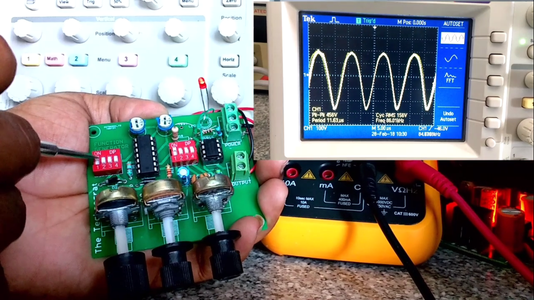


Once you have done all the soldering Connect the output of the signal generator to the oscilloscope and set the oscilloscope frequency and amplitude scale to correct value.
I used my homemade +/-12 volt dual power supply.
The DIP switches can be used to select the type of signal and the frequency range.
For example: if S1 is at X10 position and R1 is varied over the full range, then the out frequency from signal generator is from 10Hz to 100Hz.
Similarly if the switch is at X100, then the output frequency is from 100 Hz to 1000Hz.
Vary the 5 Kohm Pot connected to the op-amp and can be used to vary the signal amplitude.
Adjust the 100 Kohm presets using a screw-driver to get the Sine wave with minimum distortion.
The 1K0hm Pot is used to vary the duty cycle of the Square wave. Adjust it to 50% when using Sine wave and triangle wave.
Step 5: Debug and Finishing!!

If the circuit does not work as intended, here are the list of things you can do to debug the circuit.
Double check the connections and make sure there are no loose connections in the PCB. Check if the ICs are over heated. IF so there are chances of faulty IC. Recheck the Connections and try with a new IC. It is a common tendency to get warm, do not worry. Connect the Output of the signal generator IC(8038) to the Oscilloscope.(Test point in my PCB). This helps you to verify if your 8038 IC is working fine. If you are getting signal from 8038 and the output of op-amp stage is not correct(The final output), then the op-amp might be faulty or try to replace the resistor values. Calculate the resistor values using op-amp inverting amplifier formula. IF you couldn't solve the issue, please let me know in the comments section below. I will try to help as much as I can. or you can e-mail me.
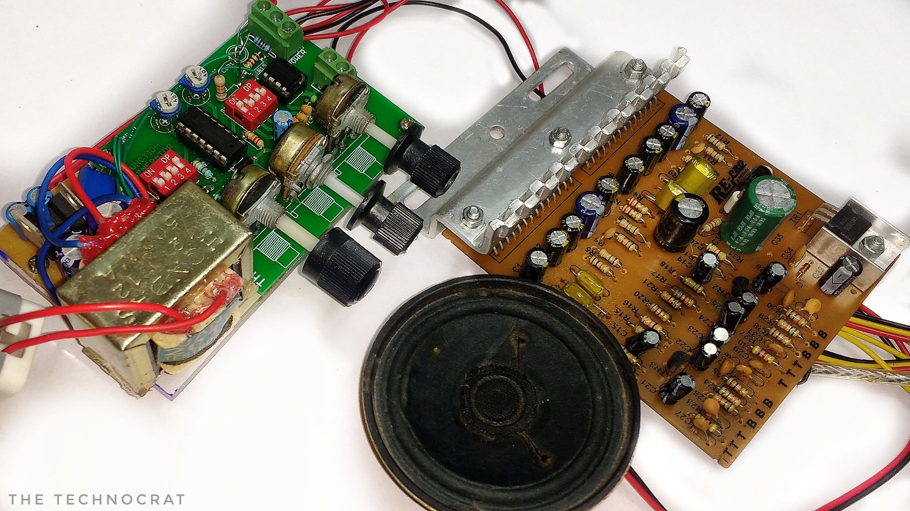
After the Successful testing I assembled the PCB and Power supply board on a piece of Acrylic Sheet.
I have been using this circuit for a while now for testing op-amp circuits. This is working for me very well for low frequencies up-to 100 kilo-hertz. The down side is that you will need a oscilloscope to visualize the wave-forms. So in the coming videos lets build a circuit to measure the frequency and amplitude of signals with a display for convenient use of this signal generator. Subscribe to my channel for the updates and more projects like this.


