

Introduction: LED Eclipse With Touch Sensors and MIDI


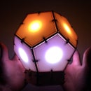


The LED eclipse is an interactive instrument with LEDs, capacitive touch sensors, and a MIDI output all controlled with an Arduino Uno. You can program the device in many different ways. Across all the applications, the idea is pretty much the same: determine which sensors are touched and then update the LEDs and MIDI output. In the video posted here, you can check out some of the programs that I wrote. The chassis is made out of MDF and was inspired by laser cut topographical maps that I saw on instructables.
I was motivated to create the device because I wanted to make more interactive light devices that added a new spin to LED tables. Due to some problems I had with the IR sensors in my geodesic dome project, another goal for the LED eclipse was to implement more reliable sensors. I chose capacitive touch sensors, which are better at providing clean signal for each sensor without having to adjust trim-pots like with the IR sensors. I also wanted to make a smaller device that was easier to assemble and transport.
In this instructable, I will go over setting up ten capacitive touch sensors with an Arduino, the WS2801 LED pixel strip, and MIDI output. Let's get started building the eclipse!
Step 1: Supply List


Materials:
1. Arduino Uno (Atmega328 - assembled)
2. 30 boards of 45cm x 45cm medium density fiberboard (MDF) with 3mm thickness
3. 1/16" thick Acrylic for diffusing LEDs (https://www.amazon.com/gp/product/B00DCKOH3G/ref=o...
4. 9V 2A Power supply (https://www.amazon.com/gp/product/B0194B7TKO/ref=o...
5. Addressable RGB LEDs (https://www.amazon.com/gp/product/B0192X56MM/ref=o...
6. Copper foil tape (https://www.amazon.com/gp/product/B00Z8MCK6M/ref=o...
7. Buck converter for Arduino (RioRand LM2596 DC-DC Buck Converter 1.23V-30V)
8. Pin Headers (Gikfun 1 x 40 Pin 2.54mm Single Row Breakaway Male Pin Header)
9. USB extension (https://www.amazon.com/gp/product/B002M8VBIS/ref=o...
10. DC power jack socket (https://www.amazon.com/gp/product/B01LQGESUO/)
11. Male DC 2.1mm x 5.5mm Barrel Plug Socket (https://www.amazon.com/gp/product/B01GPL8MVG/ref=o...
12. MIDI to USB cable (https://www.amazon.com/gp/product/B071KLC884/ref=o...
13. MIDI jack (https://www.amazon.com/gp/product/B00MEI42PU/ref=o...
14. Wire wrap (https://www.amazon.com/gp/product/B008AGUABU/ref=o...
15. One 5.5MΩ Resistor
16. Ten 1kΩ Resistors
17. Two 220Ω Resistors
18. 5/16 inch diameter dowel rod
19. Hardware (https://www.amazon.com/gp/product/B06XQMBDMX/ref=o...
Tools:
1. Laser cutter
2. Orbital sander
3. Super glue
4. Hot glue gun
5. Soldering iron
6. Wire wrap tool
Step 2: System Overview

The LED eclipse uses capacitive touch sensors positioned around the perimeter of the device to control ten LEDs and a MIDI signal. Pin 2 acts as the send pin for the capacitive touch sensors so a 5.5MΩ resistor is connected to pin 2 to ten different copper sheets. A 1kΩ resistor is connected between each receive pin (pins 3 to 12) and the copper sheet. For a review on capacitive touch sensors, check out my other instructable.
LEDs from the LED strip are also positioned around the perimeter of the device, and the signal and clock pins are connected to pins A0 and A1 of the Arduino. For a review on LED strips and Arduino, check out this link. Finally, the signal pin of the MIDI jack is connected to the transmit pin (i.e. pin 1).
In the code, the Arduino sends a pulse from pin 2 and makes a digital read at one of the receive pins of the capacitive touch sensors. A pulse is sent and detected for each capacitive touch sensor. Depending on the readings of the sensors, the Arduino changes the color of the LEDs and/or produces a MIDI signal.
Step 3: Designing and Cutting the Box


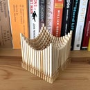
I primarily used Autocad for designing the LED eclipse box. Later I uploaded the files to Fusion 360 because I am just learning how to use it. First, I designed the entire structure as a solid piece. I wanted to try stacking cross sections after laser cutting MDF, so I then sliced the solid structure into 30 pieces. After slicing the structure, I added additional compartments that would be required for mounting the LEDs, Arduino, Buck converter, and sensors.
After completing all the cross sections, the file was exported as a .pdf and uploaded into Corel draw. I had to make a few adjustments (e.g. removing extra lines) before exporting the file as a .cdr for cutting with a laser cutter. A 45cm x 45cm sheet of MDF was then placed in the laser cutter for each layer. All files are uploaded here. There were a few extra supports that prevented the LEDs from locking into place. It is not difficult to fix these mistakes by cutting the supports out with a box cutter.
The acrylic was sanded with an orbital sander to diffuse the light from the LEDs, and was then also cut by the laser cutter so that it fit in the ring chassis.

Step 4: Assembling the Top of the Ring


The ring was assembled one layer at a time by using the dowel rods as guides for sliding the pieces together. Each layer was glued together using super glue. After placing the first two layers together, the acrylic was glued into place. The process was continued until reaching the layer that the LEDs are mounted.
Step 5: Mounting the LEDs


The LEDs were mounted on the 15th layer by pushing them through the hole and gluing them with hot glue. I designed the chassis so that the holes were spaced for every other LED on the WS2801 Pixel LED String. Instead of cutting the strip, I just taped every other light on the strip with electrical tape.
In the uploaded .cdr file, the holes are a little too small so I used a box cutter to widen the holes. After the LEDs are firmly attached, the layer was added to the top part of the chassis.
At this point, I tested the LEDs using the attached code, which requires the Adafruit WS2801 library.
Attachments
Step 6: Touch Pad Assembly


After assembling and testing the LEDs, I assembled the rest of the layers until layer 24 by sliding them onto the dowel rods and gluing them down. Several of the supports needed to be cut so that the LEDs fit in.
Before mounting the MDF touch pads on at layer 24, I traced the pad shape onto the back of the copper strip and cut the copper for the pads. The MDF pad was then glued into place and the adhesive part of the copper was placed on the MDF. The 1kΩ and 5.5MΩ resistors were then soldered onto the copper.
Step 7: Front Panel and Bottom Plate Assembly


After mounting the sensors, layers 25-27 are mounted as previously described. Layers 28 and 29 are assembled separately. M5 nuts are glued into place with hot glue. These nuts are required for fastening the bottom plate to the chassis. The bottom plate can then be attached with M5x16 bolts. Layers 28 and 29 were then glued to the rest of the assembly.
The front panel consists of a jack for the power supply jack, switch, MIDI jack, and USB jack extension cable for the Arduino. All these components were glued or screwed onto the front panel and cables were soldered to the MIDI jack, power supply jack, and switch. The 220Ω resistors were also soldered to the MIDI jack as shown here. Finally, the panel was slid into place and glued.
Step 8: Wiring the Electronics


The Arduino requires a 9V and the LEDs require 5V, so I used a 9V 2A power supply and Buck converter to power the LED eclipse. I soldered the Buck converter to prototype board using header pins. The one end of the switch and one end of the power jack were then soldered to the input of the Buck converter. Using a voltmeter, the Buck converter was adjusted to 5V. The Male DC 2.1mm x 5.5mm Barrel Plug was also soldered to the prototype board at 9V and connected to the Arduino.
Next wire wrap was wrapped around the resistors connected to the copper using a wire wrap tool. The wire was connected as shown in the schematic. Header pins were connected into pins 1-12 so it was easy to connect the copper and MIDI jack to the Arduino.
Step 9: Programming the Ring


The LED eclipse can be programmed in countless ways. Generally, the input from the capacitive sensors are read into the Arduino, and the LEDs and MIDI are updated based on the sensor values. I have three example programs here: (1) The ring is lit as a rainbow and plays arpeggios, (2) the ring is lit white and produces rotating patterns when a sensor is pressed, and (3) Simon.
All these programs require the MIDI library by Francois Best and LED strip library by Adafruit.

First Prize in the
LED Contest 2017

Participated in the
Arduino Contest 2017

Participated in the
Epilog Challenge 9


