

Introduction: Make Your Own High Quality CO2 Lasercutter! With Touch Control!


Hello everybody
About a year ago, I wanted to buy a CO2 lasercutter to make my workspace complete. One problem was that lasercutters aren't cheap, especially not for hobbyists who want a large cutting area. Of course, for that price you also get awesome software and customer support when you buy a lasercutter, but I only turned 17 when I started this project and I just didn't have that money. That is why I built my own machine. I had already made a machine like this, so I thought: "Why not do it again?". Of course this one wouldn't be made out of MDF sheets.
I made this machine together with my friend Thibo as it was our integrated project for school (we are in our last year of industrial sciences). He focussed on the research about lasers and cutting with a laser, because it's amazing that you can cut objects just by using light. I focussed on building this machine. In this instruction, there will only be talked about the lasercutter itself. This is a full step by step instruction on how to build your own lasercutter! I've included every file you need for building it in this instructable.
This lasercutter uses a 40 W CO2 laser, has a large cutting area of 1000 by 600 mm and has a touchscreen to control it! The entire project cost me about €1900, this is still a lot of money, but I didn't want to make it from scrap. It needed to be built from high quality materials so it wouldn't fall apart within two years. And it's still very cheap for a lasercutter with such a large cutting area. Plus, for this price, you get an awesome experience of building your own lasercutter and invaluable knowledge.
It runs on two microcontrollers, an arduino with GRBL and a raspberry pi with touchscreen to make this a stand alone device and control it. This means that you don't need a computer to send files to your machine. Unfortunately I don't have time for this at the moment, so the touchscreen is now just used for controlling extra features like the lights, air assist, pump... I will definitely continue working on this project to make it a stand alone device.
Important! This machine uses a 40W laser! I took good precautions when designing the enclosure and the laser will be only activated when the cover is closed. Allways use safety goggles when testing the laser. Even reflections of the beam are very dangerous for your eyes! I'm not responsible for eventual accidents.
I really hope you like my instructable and it will help some of you building your own machine!
I uploaded a video of this lasercutter on youtube, you can find it here:
Step 1: Design


In this step, I will talk about the design of this machine. This step doesn't include any files to download. I will add those files in the steps where I talk about building or assembling the seperate parts of the lasercutter. As for this step, I'll just explain how and why I got to this design. I was inspired by the hobby series lasercutter from Full Spectrum Laser for the exterior design of the lasercutter.
Before making a draft of what the machine should look like, I made a list of things that needed to be kept in mind when designing it.
First one in line: safety! When building a machine like this, safety is a priority. As this lasercutter uses a 40 W CO2 laser, it is obvious that the laser beam and even reflections of it(!) need to be kept inside the machine. Therefore I use a dark acrylic plate for the cover. The plate is just transparant enough for you to see what happens inside.
For the side panels I used high pressure laminate, just because it looks good and is laser resistant.
The second factor I kept in mind was how big the working area and the cutter itself would be. I wanted it to have a large cutting area of 600 by 1000 millimeters. Why build a small machine when you can build a big one?
Since this is still a DIY machine, I wanted it to be easy to change or add parts when needed. Therefore the margins of all the seperate 'rooms' in the machine are picked a little bit spacious.
With the ease of building and potentially modifying this lasercutter in mind I decided to build the frame out of 3030 Aluminium T-slot profiles.
Now I will explain the basic design of this project. In the pictures of this step, I added some drafts that show you the different views of the frame. The construction consists of five seperate places. The biggest space of all, is the working area of the lasercutter. The space right behind the working area is the ventilation room, all fumes will be sucked from the working area to this place and they will be exported outside by a ventilation hose. Behind the ventilation room, there are two spaces on top of each other. The upper space is the space where the laser wil come. I wanted the laser not to be in the working area because it would be bad for the laser to be in all those fumes. The lower space is the space where the water tank and waterpump will be, these are necessary for the cooling of the laser. The last room is the space on the right of the machine, where all the eclectronics, drivers, supplies and touchscreen will be. The seperate spaces will be seperated by 3 mm acrylic.
Step 2: Bill of Materials

As usual, I've made a complete bill of materials with everything you need to build your own lasercutter. Most of the parts are ordered on aliexpress, some of them on ebay and the rest you can find in your local DIY-company. The total price of these parts is about €1800. The only things not included in this price are shipping costs (a total of about €50) and the 3D printer filament. I used a bit less than two rolls PLA filament (€40) for printing all the parts. The total costs for this awesome lasercutter are about €1900.
In the BOM, the individual plates aren't mentioned because you'll get more information about them in step 7. I just spent a total of circa €350 on those plates.
I also just mentioned 'nuts and bolts' in the BOM. If you look at the picture I uploaded in this step, you'll see exactly which nuts and bolts (with DIN number) and how many of them I bought. I don't really know how many of them I used but the quantity I mentioned will certainly do.
I've chosen a laser head with movable lens, so you can adjust the Z-distance between the lens and the material you want to cut to set the focal point right.
Attachments

Step 3: 3D Print Some Things

A lot of the parts of this lasercutter are made with the help of my 3D-printer. I've uploaded all the files that need to be 3D-printed before you can start building your own machine. In the names of these STL-files I mentioned how many times each part needs to be printed. The names of the parts are written in Dutch, sorry for that, but normally this shouldn't be a problem.
You can see some of these parts in the image, but not all of them are included there.
The colour of the parts doesn't really matter, but I printed all of the inner parts in red (because we liked it) and the exterior parts in black (and some inner parts, just because I ran out of red filament ;)).
If you don't own a 3D-printer and don't know anyone with a printer, you don't have to buy one yourself. You can just use a 3D-printing service like 3D hubs, it's very easy.
A 3D printer is a beautiful investment though.
Attachments
Step 4: Cut the Profiles


As I already mentioned in the bill of materials, I ordered the aluminium profiles with a length of 1980 mm in Germany. I made a scheme of which parts can be cut out of every profile, i added it in this step. Some of the profiles need to be cut in a bevel of 22,5° to make the bezel in the front of the lasercutter, other profiles need to have a hole drilled or tapped thread in it. That last one is for extra fastness of the frame. I added the drafts of edited profiles in this step.
The tools needed for this are actually just a metal saw. I had access to a circular saw and a belt sander, so cutting the profiles was a pretty easy job, but it still took a day's work for two people. You just need to cut the profiles like I drew them for you in the attachment and everything will be all right.
Attachments
Step 5: Assemble the Frame


The frame was assembled using 3D printed pieces. Those pieces can be downloaded in step 3. You can use those or buy iron pieces for extra fastness. You also need to print the hinges and 'voet deksel' to assemble the cover.
To assemble the profile, just start by assembling the bottom profiles, then the vertical profiles, the upper ones and last of all the middle profiles. The cover can be mounted when the rest is done. In the attachments of this step I included a guide that says which profiles that need to be mounted and where.

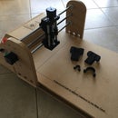
Step 6: Mount the Rails and Motors


Now that we have the full frame of our lasercutter, it's very easy to mount all the rails, stepper motors and other parts. It's best to do this before mounting the plates because you have easy access to everything now.
To mount those parts, just look at the pictures how I did it, I think this is the easiest way to explain it. The only thing you need to change is the limit switch of the X-axis. It's mounted at the furthest point of the axis and it needs to be placed on the nearest point. This needs to change because in the software we'll use (inkscape), the zero position is placed in the lower left corner. Normal lasercutters use the upper left corner, but this doesn't really change anything on the quality of your cuts, so the lower left corner of the working area will be used as home position.
I also changed the mirror holder mounted on the Y-axis, You need to mount it on the same spot, but i just changed its design to be a bit more resistant to vibrations of the axis caused by its movements.
Also, be very (!) careful when sliding the linear bearings on the rails for the first time. If you do it wrong, you'll lose the little balls of the bearing and this would be very annoying.
Step 7: Cut and Bend the Plates


In my school, we have a cnc miller, so the plates were cut by one of my teachers. I guess not many of you have a cnc miller at home. That's not a problem! Almost every supplier of acrylic sheets offers cnc cutting them for a cheap price. I included the .dxf files of all of the plates that have to be cut for the lasercutter in this step. The side panels of my machine are 12 mm. They're so thick because we didn't have smaller sheets at school and I liked the combiation of the dark plexi and the high pressure laminate. The thickness of the side panels actually doesn't matter. In the names of the files, I mentioned the thickness, the material, the color and the quantity of the plates.
The 8 mm dark acrylic sheet used for the cover needs to be cut as well. Two of these sheets need to be bent to fit the bezel, I contacted a local company for this. The files with the dimensions of the bevel are also included in this step. Again, with this sheet, I used 8 mm acrylic because I could buy them for a very reasonable price. I would recommend you to use 6 or 4 mm acrylic for the cover because: 1. It's cheaper if you need to buy them at full price. 2. The cover won't be as heavy as it is now. 3. It will be cheaper and easier to bend the plates.
We also need an 18 mm MDF sheet as the base for the working area. Normal hobby lasercutters use a honeycomb table or something like that, but such a grid costs way too much for the dimensions of this lasercutter. So I decided to use an MDF sheet instead. Normally it shouldn't give problems, but I would still recommend fireproof MDF (yes, it exists) for this use.
Attachments
Step 8: Mount (most Of) the Plates


Now that we have mounted the axis, stepper motors and other (3D printed) parts, it's time to mount the plates. I mounted almost every plate, except for the back plate and the side plate on the side of the electronics. There still are some parts like the electronics, laser, water tank... that have to be mounted there, so those rooms need to be left open.
Also, between the profiles and every plate of the ventilation area, i glued an 'air strip' (I don't know how you call it in English, but we call it 'tochtstrip'), you can see it in the pictures. This strip prevents the fumes to escape the ventilation room between the profiles and the plates. This is highly recommended!
Step 9: Add the Laser, Water Cooling Circuit and Fans


Because a 40 W CO2 laser will be used, the laser itself needs to be cooled. This will be done by watercooling. I made the water tank out of an old 90 mm PVC pipe (800 mm long). The water will be pumped from the tank to the laser, to copper pipes for cooling the water and then back into the tank.
For the copper pipes, i bought three 12 mm copper pipes of 1 m together with two female to female elbows and two male to female elbows and just soldered them like you can see on the picture. The copper pipes will be mounted inside the ventilation room, so the ten computerfans mounted in a row on the other plate will constantly blow air on the pipes so they will be able to cool down the water. This way, the fans won't only extract the fumes from the working area but also cool down the coolingwater.
As I just mentioned, ten computer fans will be mounted in the back of the working area to extract the fumes. In most of the pictures in this instructable, they're mounted on the back of the plate with a filter in front of them, so the fans are actually inside the ventillation room. I had to change this because the flow rate of the fans was reduced a lot. This was because there wasn't enough space behind the fans and the filter, that also resisted too much. Now, the fans are mounted in the front of their plate and they're much more effective.
I drew a sketch of how the tubes for the cooling water are connected to the elements. You can see the direction of the water flow on the pump.
Step 10: Electronics


The electronics may look difficult on the pictures, but it's actually very simple. There are two power supplies, one 12 V for the fans, pump and motors and one 5 V supply that powers the microcontrollers. The arduino is just connected to the steppermotor drivers and the driver of the CO2 laser. The Raspberry pi is just connected to some buttons. One button to detect if the cover is closed and another one is the emergency stop. The raspberry Pi also controls the relay module. The other parts you can see are a relay for the emergency stop circuit and a solid state relay to turn off the power to the laser when the cover is open.
All the electronics that are being used are mentioned in the B.O.M., except for two resistors (825 Ohm) and two capacitors (1000µF). I mounted the power supplies, arduino, stepper motor drivers, and relays on a plate, this makes it easy to work on it. You can see the lay-out of the electronics in the pictures.
I included the full wiring diagram for all the drivers and microcontrollers, the best way to wire them is to print the diagram and just mark which wires you already connected, so you'll know what you've already done. It's a pretty simple job actually.
I added two resistors to the homing circuit on the arduino. The arduino already has internal pull-up resistors, but they're too weak and won't work the way we want.
The stepper motor drivers are set on 16 microsteps, this means that every step of the motors is divided in 16 seperate steps. That way, our stepper motors will need to do 3200 steps per revolution with microsteps instead of 200. The driver for the motors of the y-axis needs to be set on 3,3A because two stepper motors are connected in parallel there. The one for the x-axis can be set on 1,8A. I also connected a 25V 1000µF capacitor on the power lines of the drivers, this prevents interferences on the power lines.
Attachments
Step 11: Setup Your Arduino

A lasercutter works with Gcodes. These are codes that tell the machine what kind of movement it needs to do and where it needs to go. For that we need a Gcode interpreter. This device reads the codes from your computer (or raspberry pi with touchscreen) and converts them into pulses for the steppermotor drivers and laser driver.
I used an arduino running on GRBL as gcode interpreter. GRBL is free and open source software.
First of all, you need to install the latest version of the arduino IDE on your computer if you don't have it already. This makes it possible for your computer to recognise the arduino and compile GRBL to it.
You can download the latest version of GRBL here.
Before we can compile GRBL, you need to edit some part of the code to make homing (returning to its home position) possible. Extract the .zip file, go to the folder 'grbl' and open the config file with wordpad. Use crtl-F to find 'homing' and search until you find "#define HOMING_INIT_LOCK". Change it to "// #define HOMING_INIT_LOCK". This makes homing optional and not required before running a job. Four other things that need to be changed are:
" #define HOMING_CYCLE_0 (1...Z_AXIS) ", Comment this line. (Add "//" at the beginning of the line)
" #define HOMING_CYCLE_1 ((1...X_AXIS)|(1...Y_AXIS)) ", Comment this line.
" // #define HOMING_CYCLE_0 (1...X_AXIS) ", Uncomment this line. (remove "//")
" // #define HOMING_CYCLE_1 (1...Y_AXIS) ", Uncomment this line.
The "..." need to be replaced with those arrows, but I can't type them here because there is probably a bug or something here.
These changes tell GRBL that we don't use a Z-axis, this is necessary because when the lasercutter wants to return to its home position, it would home the Z axis first. Don't forget to hit save when closing wordpad.
Now that grbl can be compiled to the arduino, I will refer to the GRBL compiling page.
When that's done, open the arduino IDE again and open the serial monitor (right upper corner). First set the baud rate to 115200 and type '$$'. Now some values need to be changed. You can see the values that need to be changed in the image I uploaded in this step. If you want more information on what all those numbers are, check out this page.
Step 12: Setup the Raspberry Pi


For now, I have only written a simple piece of code for the raspberry pi with four pushbuttons to control the lights and other functions. It also does some safety checks before turning on the laser. As I already said, the aim is to build a stand alone lasercutter, which means that the raspberry will read the codes from a USB drive and send them one by one to the arduino. You won't need a computer then. Unfortunately I don't have time at the moment to do that so for now I've just written a simple code.
I've uploaded an image file of my SD card, so the only thing you need to do is download the image file and use win32diskimager to write the file to a 4GB SD card.
For those who want to edit the code or want to keep developing the code to give it more functionallities, I've also uploaded the code itself. It's written in C# with Visual Studio 2017.
UPDATE: I have removed the raspberry pi and touchscreen from my lasercutter and just replaced it with four switches (for enabeling ventilation, cooling, lights and air assist). I'm still planning on updating the raspberry to make it a stand alone device, but I can't find the time for that right now.
Step 13: Calibrate the Mirrors

Now the electronics and the software is done, we are almost ready to use the lasercutter. The only thing left to do is calibrate the mirrors for guiding the laser beam to the right location. This is important and needs to be done correctly because as you know, the laser beam is guided to the right direction with the use of mirrors. If one of the mirrors is reflecting to the wrong direction, beam will not arrive at the right place or it wil burn something that doesn't need to be burned.
To do this, take a piece of wood or cardboard or something and stick it with double sided tape on the second mirror (the one that moves along with the Y-axis). Slide the Y-axis to the nearest point of the first mirror (the one next to the laser itself). Quickly push the testbutton on the laser driver. Now the laser has marked the piece of wood with a dot. Now, slide the Y-axis to the furthest point of the axis and push the testbutton again. The laser will have marked another dot on the wooden piece. The aim is that the two dots are perfectly on the same spot. So you'll need to repeat this several times with a new piece of wood. Between each session you need to adjust the first mirror by turning those bolts. Try to have that spot in the center of the mirrors, adjust their location before aligning them.
When the first mirror is calibrated, you can do exactly the same for the second mirror.
For the last mirror, the one that leads the beam downwards into the lens, I just adjusted the mirror until the beam was perfectly vertical.
You'll see, this is very easy and only takes 15 minutes of your time. After several working houres of your lasercutter, you'll have to redo this step.
Step 14: Mount the Last Plates


When the laser is calibrated correctly and everything is tested, the last plates can be mounted on the construction. Now the exhaust pipe, the cooling fans for the electronics and the power plug can also be mounted on the backplate.
Step 15: How to Use Your Lasercutter?

To use this lasercutter, G-codes need to be generated and sent to the arduino.
There are two ways to use a lasercutter, vector mode and raster mode. In vector mode, the contour of an object will be cut or engraved. In raster mode, the object itself wil be engraved and not only the contour.
To design the objects that need to be cut, i use inkscape V0.91. With two extensions for generating the G-codes. One for vector mode. And another one for raster mode. You can also import files like .svg, .dxf, .jpeg...
For sending the G-codes to the arduino, LaserGRBL is being used.
Those are all the files and programs you need for letting the lasercutter do its job. Remember that the laser itself will only work when the pump is activated and the cover is closed.
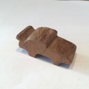
Step 16: Create!


Now you have your own awesome CO2 lasercutter. Once you have a machine like this, the sky is the limit! You can really make anything you want! I've already made tons of key rings, greyscale pictures, boxes, birthday cards and even a simple duck!
This was a really fun project, I worked day and night on designing, building, programming and testing of this lasercutter and I truly loved every second of it! Making machines like this has become a passion in the last years and I'd love to continue doing things like this in my life!
I really hope you like this project as much as I do! If you liked my instructable, please vote for me, I would really appreciate that. I'd love to compare the prestations of this lasercutter to a professional one.

Runner Up in the
Lights Contest 2017

Grand Prize in the
Microcontroller Contest 2017

Second Prize in the
Design Now: In Motion Contest


