

Introduction: ☠WEEDINATOR☠ Part 1: Drive Mechanism


In the world of professional agriculture, a lot of focus has been put on large, incredibly expensive machines that work in huge open fields where just one crop is grown. Whilst this is incredibly efficient and produces very cheap food, it's not good for pretty much everything else!
There does exist a substantial backlash against this farming model where small farmers grow 'organic' vegetables on small farms with respect to the environment and indigenous wildlife. Some might call this the 'Permaculture' movement, but I'm really not sure if permaculture would embrace modern 'robot' technology or not as historically robots take away people's jobs and help destroy communities.
Anyway, here I introduce the Weedinator - an autonomous agricultural electric tractor that can be used on small farms to cultivate, till, plant and weed seed beds. It will be able to travel up and down 56 inch wide beds, several times a day if necessary, performing a multitude of quite delicate tasks which a big tractor might struggle with. Some of the key advantages are:
- Less need for heavy cultivation such as ploughing which destroys soil structure.
- Preservation of soil health by keeping essential natural micro-organisms and nutrients near the top of the seed bed rather than burying them.
- No fumes or pollution especially in glasshouses or polytunnels.
- Will help small farms compete financially with big industrial producers.
Will the Weedinator destroy jobs or will it encourage lots more people to set up small farms and help protect the environment? (Let me know what you think).
So if you want to build an autonomous tractor, where do you start? In part 1 of this project I'm just going to show how to build the drive mechanism - it's all about welding and fabrication and there's nothing much about the electronics ..... yet. The aim is to get a solid mechanical system working in 3 axes -
- Drive
- Steering and
- Suspension
Eventually, as the project progresses, the chassis will become populated with all kinds of weird and wonderful gadgetry including a digital compass, GPS positioning, GPRS , object recognition ..... The list goes on! Looking into the crystal ball, imagine a huge 200 kg drone that moves at about 1 mph along the ground fitted with an onboard CNC machine.
Step 1: Welding Safety

- Never look at the welding arc either directly or otherwise and protect other people and animals and anything else with eyes from the same. It's your responsibility to protect others from blindness.
- Always wear a mask and never expose any skin to the powerful UV light emitted from the arc. This also means legs and arms and neck. Never do welding in shorts and T shirt. UV light can cause skin cancer.
- Check very carefully for flammable materials in the work zone, particularly piles of sawdust. A blob of metal can easily fly off and land in a dark corner somewhere to gently smoulder - you go away for 1/2 an hour and come back to your shed on fire.
- Be aware that it's surprisingly easy to set your own clothing on fire, particularly your underpants.
- Long hair should be tied up to avoid catching fire.
- Make sure there is adequate ventilation, especially if you are welding inside a tight space.
- Keep a suitable fire extinguisher close to hand.
- If you want to look cool and protect you scalp from hot blobs of molten metal, wear a baseball cap back to front. Traditionally, this should be as brightly coloured as possible, preferably with a floral pattern!
Step 2: Tools and Equipment

- MIG welder on CO2 or Argon mix
- Plummer's wrench
- Grinder
- Drill
- Clamps
- Files
- Leather / hide / copper head hammer
- Set square
- Vernier calipers
- Emery paper
- Spanners and socket set
- Gauntlet gloves
- Auto react welding helmet
The welder needs to be of at least 180 amps with a good quality feed mechanism for 0.8mm wire. Be aware of the cheaper Chinese models as they are generally useless.  Keep the welding nozzle clean of splatter to ensure clean wire feed.
Step 3: Drawings


Drawing files are attached!
Attachments
 001 Suspension Motor Attachment Plate 02.dwg
- 002 Swivelling Suspension Motor Bracket 02.dwg
- 003 Suspension Motor Upright Plate 03.dwg
- 004 Plate on Top of Channel 02.dwg
- 005 Vertical Plate on Channel 02.dwg
- 006 Horizontal Static Brackets 02.dwg
- 007 Suspension Wishbone 03.dwg
- 008 Lower Suspension Rod Vertical Bracket 02.dwg
- 009 Vertical Suspension Plate 02.dwg
- 010 Upper Gearbox Gusset 02.dwg
- 011 Wheel Attach Disc 02.dwg
- 012 Wheel Disc Gusset 02.dwg
- 013 Lower Gearbox Vertical Plate 02.dwg
- 014 Lower Gearbox Horizontal Plate 02.dwg
- 015 Upper Gearbox Horizontal Plate 03.dwg
- 016 Steering Sensor Plate 02.dwg
- 017 Upper Gearbox Vertical Plate 03.dwg
- 018 Lower Suspension Rod Horizontal Plate 02.dwg
- 019 wishbone joining plate.dwg
- Lower Gearbox Vertical Plate Gusset 02.dwg
- Motor adapter sleeve 01 Model (1).pdf
- Motor adapter sleeve 01.dwg
- Steering Gearbox shaft 01 Model (1).pdf
- Steering Gearbox shaft 01.dwg
- Suspension Tube A 03 Model (1).pdf
- Suspension Tube A 03.dwg
- Transmission Gearbox shaft 01 Model (1).pdf
- Transmission Gearbox shaft 01.dwg


Step 4: Components


Raw Materials:
- Round bar, bright, 20mm x 1000mm
- Round bar, bright, 25mm x 320mm
- Round bar, bright, 40mm x 1000mm
- Round bar, bright, 50mm x 300mm
Parts:
- Laser cut parts - see drawings attached.
- Turned and milled parts - see drawings attached.
- Motors and suspension spindle
- Deep roller bearings - 32 x 20 x 7mm ... 12 of
- Slimline pillow block bearing 45mm .... 1 of
- Slimline pillow block bearing 25mm .... 2 of
- Pulley wheel SPZ132/1 ...... 1 of
- Circlips diameters 25, D1400-025 .... 2 of
- Circlips diameter 15, D1400-015 .... 8 of
- Nuts and bolts, various.
- 200 x 100 x 5 x 305 box section
- Quad bike wheel
- M860H stepper controller .... 3 of
- Arduino Nano
- 13 nm stepper motor nema 34 .... 1 of
- 8 Nm NEMA 34 stepper motor ... 1 of
- Non-captive (spindle does NOT turn) 8 Nm MEMA 34 stepper motor ... 1 of
- 750mm spindle for above with M14 thread on both ends.
- 6mm key steel
- 100:1 gearboxes NEMA 34 ... 2 of
Special thanks to DMM Llanberis for allowing me to use their lathes and milling machine!
Step 5: Steering Sub-assembly


The steering shaft ends on a 50mm cylinder and uses a low profile 45mm pillow bearing block to sustain the leverage forces created by the offset of the wheel to the centre line of the steering. The bearing is bolted into place and is used to ensure correct positioning of all the other components. Tack welds are made with 6 second blasts of the MIG welder at high power in strategic positions which allow both strength and the ability to remove the weld at a later stage. All tack welds should be accessible by either a grinder or a drill bit for removal in case of a positioning mistake (see one of the later stages).
Clamps are used to locate the bracing gussets.
Step 6: Drive Subassembly


An 18" stilsons or plumber's wrench is the ideal tool to bend small pieces of metal in a vice. The part shown is deliberately designed with slots where the bends need to be - the bend will naturally occur along the slots, which are welded up afterwards.
The 25mm pillow block bearings ensure that the steel plates are in the correct position before the gusset is clamped on and welded tight.
Step 7: Joining Steering to Drive


The 50mm free end of the steering shaft is tack welded to the top of the drive gearbox. The sheer weight of the steering sub assembly prevents distortion of the joint, as long as the tack welds are positioned in sequential opposite pairs and not all welded on one side and then the other. Distortion is the arch enemy of the welder and is often caused after a large, hot weld cools down and shrinks.
Always tack weld on opposing, opposite sides of a component to help prevent distortion.
Step 8: Suspension Wishbones


The suspension needs to be positioned such that none of the moving components crash into one another. This mechanism is quite complex, so it's easy to get the position slightly wrong, which is why it's important to use tack welds appropriately. The first time I welded in the suspension I got it slightly wrong and so had to grind out and drill out some of the welds. Fortunately all of the welds were accessible although I did break a couple of drill bits in the process.
Step 9: Suspension Motor Subassembly


The suspension is driven by a stepper motor on a 14mm spindle and is most easily put together on the bench as shown before positioning on the main drive system.
Step 10: Wheel Disc


The wheel is attached by means of a steel disc, which itself is attached to the drive shaft with 4 small gussets. The gussets are cut so accurately that they can be used to align the disc itself so avoiding a wobbly wheel.
Note that the welder's earth lead is placed close to the welding zone and not to any other arbitrary part of the assembly - this is very important as otherwise current could pass through the bearings and cause a small weld within the bearing itself which would effectively ruin it.
Step 11: Motor Attachment

A small tube with a slot milled on it is used to allow the motor shaft to fit into the gearbox (see drawing). Small 4mm cone seated grub screws are used to secure the tube to the motor and a key is inserted in the slot to match up to the slot within the gearbox. A file is used to make the key itself from a length of 6mm square key steel.
Step 12: Test Bed Electronics

Since this is more about the mechanism, the electronics used is currently very basic - a simple stepper motor controller and an Arduino Nano - just enough to get the motors working with some acceleration.
The controller is a M860H which is supposed to give up to 7 amps at 50V, but I could only squeeze out 2.6 amps before the main drive motor started to miss steps. Nonetheless, it gave quite some considerable torque which seemed large enough to propel the vehicle forward. I'm going to try another system - a closed loop stepper motor setup which is a lot more sophisticated and reportedly gives better torque performance.
Step 13: Arduino Test Code
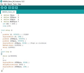
#  define CSpin    3
#  define STEPpin  5
#  define DIRpin   6
#  define RESETpin 7
  int del = 2000 ;
  long i=0;
void setup ()
{
  pinMode (8, OUTPUT) ; //SLEEP
  digitalWrite (8, LOW) ;
  pinMode (STEPpin, OUTPUT) ;
  pinMode (DIRpin, OUTPUT) ;
  digitalWrite (DIRpin, HIGH) ; //High is clockwise
  Serial.begin (115200) ;
  delay (10000);
}
void loop ()
{
  while (i<500000)
  {
  i++;
  digitalWrite (STEPpin, HIGH) ;
  delayMicroseconds (800) ;
  digitalWrite (STEPpin, LOW) ;
  }
}
Step 14: Testing the Mechanism


The driver assembly was bolted to a short piece of 200 x 100 x 5mm box section and held firmly in a large bench mounted vice. Firstly, the wheel rotation was tested, which worked well with the correct speed and reasonable torque. The torque was tested by crudely trying to slow the wheel down by hand and was deemed to be adequate. Torque is directly related to the current going through the motor windings and can almost certainly improved by upgrading the motor driver to a hybrid closed circuit type, which has good reviews within the online community.
The suspension also worked well and managed to lift a considerable weight - about 75 kg. In use, the suspension will be working in reverse, acting against the chassis. Something worth noting is that the suspension did not 'unwind' when no current was applied to the motor, which is very useful.
The steering had much better 'lock' than expected, with about 120 degrees of rotation which is very much better than most normal tractors. The only downside was that it had more backlash than expected.
Step 15: Improvements


- Steering Backlash - whilst the steering system could just be used 'as is', after all, it's only travelling at 1 mile an hour, I thought it should be addressed. One possible solution is to use a cable as in the diagram above to effectively pull the wheels together, holding the backlash on one side of the gear assembly. Phil, one of the Weedinator team members, suggested incorporating Ackermann geometry into the back lash design, which could be done by using an off centre or elliptical pulley wheel for the cable. Another possible solution would be to use a separate motor on a linear actuator, similar to the suspension motor, to act as an adaptive tensioner on the cable which reacted to the Ackermann geometry programmed into the steering. This will all be covered in Weedinator part 2.
- Steering Backlash and Simplification - see video above - The steering shafts are joined together and the steering motors can be made to 'jam' against each other very slightly to take out the backlash. Simplification of the suspension could reduce possibility of rotational strains occurring in the chassis which could jam up the CNC mechanism.
- Motor torque and control can be improved by using 'Closed loop' stepper drivers and rotary encoders. Fancy electronics built into the driver prevents any steps from being lost and raises alarm signals upon finding errors. Also, torque is increased on higher speeds.
- Testing the machine at very low speed is absolutely fine but higher power and speed can be achieved by using servo motors - up to about 1KW - but these are currently way beyond my budget!
☠

Runner Up in the
Make It Move Contest 2017

Participated in the
Metal Contest 2017


