

Introduction: Nunchuk Controlled Robotic Arm (with Arduino)


Robotic arms are awesome! Factories all over the world have them, where they paint, solder and carry stuff with precision. They can also be found in space exploration, subsea remote operated vehicles, and even in medical applications!
And now you can have a cheaper version of them at your own home, office or lab! Tired of doing a repetitive job? Program your own robot to help you... or to mess things up! :D
In this tutorial I show you how to mount a robotic arm, and how to program it using an Arduino Mega. For this project I also wanted to experience a different method for controlling a robotic arm: using a Nintendo Nunchuk! They are cheap, easy to find, and have a bunch of sensors.
There are several ways you can use this tutorial. If you don't have a robotic arm kit (and doesn't want to buy or build one) you can still use it to learn something about Arduino programming, and how to interface an Wii Nunchuk to your own projects. You can also use it to practice your electronics and mechanic skills.
Step 1: Tools and Materials


The following tools and materials were used in this project:
Tools and materials:
- Solder iron and wire. I had to solder some terminals to Nunchuk's wires in order to connect it to the Arduino;
- Shrinking tube. Some pieces of shrinking tube were used for a better isolation of the conductors;
- Screwdriver. The structure is mounted using some bolts and nuts;
- 6-axis mechanical desktop robotic arm (link). This awesome kit already comes with several components as described bellow. It's reliable and easy to assemble;
- 12V power supply (2A or more);
- Nunchuk controller (link). It interfaces to the Arduino board, and it's used to control the robotic arm;
- Male jumper wires (4 wires);
- Arduino Mega (link / link / link). Notice that the robotic arm kit I've used also has a board and controller bundle that already comes with this Arduino board. If you you're not using on of those kits, you might use other Arduino boards as well;
I was informed later that there's a Nunchuk adapter that makes the connection to a breadboad easier (link / link). It's a good option if you want to same some time on soldering and doesn't want to destroy the original connector as described on Step 9.
Sain Smart 6-axis mechanical desktop arm already comes with the following components:
- Arduino Mega 2560 R3 (link)
- Control board shield (link)
- NRF24L01+ Wireless Transceiver Module (link)
- MPU6050 3-axis gyroscope and a 3-axis accelerometer (link)
- 71 x M3X8 screw
- 47 x M3 nut
- 2 x U bracket
- 5 x servo bracket
- 4 x 9kg servo (link)
- 2 x 20kg servo (link)
- 6 x metal servo tray
- 3 x U bracket
- 21 x right-angled bracket
- 3 x flange bearing
- 1 x gripper
You might find other robotic arm kits online (link), or even design your own. There are some awesome projects you can 3D print, for instance.
In the following 7 steps I'll show you how to assemble the arm kit before wiring up the circuits. If you doesn't have a similar kit, feel free to jump some steps. You can use another robotic arm kit, assemble it and jump directly to the electronics and programming steps.
At each step, there is an animated gif, showing how my robotic arm was assembled. It only runs on website's desktop version.
Step 2: Assembling the Robotic Arm Pt1 - Base


The first part to be assembled is the base of the robot.
It's made of two U shaped brackets, joined back to back using four M3 bolts and nuts, as shown in the pictures. This is propably the easiest part to be mounted.
Step 3: Assembling the Robotic Arm Pt2 - Servo #1


The first servomotor is mounted perpendicular to the base, using a servo bracket. This profile is attached to the base using four M3 bolts and nuts, as it's shown in the pictures. Servo #1 is place on it's top, and attached using four M3 bolts and nuts.
A circular metal horn is attached to the servo axis. The kit comes with several plastic horns. They won't be used for assembling the robot.
Step 4: Assembling the Robotic Arm Pt3 - Servo #2


Another servo bracket is mounted perpendicular to the previous one. It's connected to servo #1 horn using four M3 bolts. Servo #2 is installed with four M3 bolts and nuts, and also uses a circular metal horn.
An U bracket is then attached to the horn using four bolts. Notice that a M3 bolt is used oposite the servo axis. It gives stability to the structure. A bearing fits on this bolt, and it's locked in position using another M3 nut. This way the U bracket is tightly attached to servo #2 center axis.
Step 5: Assembling the Robotic Arm Pt4 - Servo #3


Another U bracket is mounted using four M3 bolts and nuts.
On the other end, servo #3 is installed, using a circular metal horn and four bolts. A servo bracket is connected to the servo motor, and a L shaped profile is linked to the servo bracket using some bolts and nuts.
Notice that another bearing is used oposite to the servo axis, as described before.
Step 6: Assembling the Robotic Arm Pt5 - Servo #4


Another U bracket is connected to the L shaped profile using a set of four M3 bolts and nuts. Similarly to the previous step, servo #4 is mounter to the U bracket using four bolts. Another servo bracket is connected to the servo.
Step 7: Assembling the Robotic Arm Pt6 - Servo #5


The fifth servo is connected perpendicular to servo #4 using another servo bracket, installed using four M3 bolts and nut.
Step 8: Assembling the Robotic Arm Pt7 - Servo #6


The gripper is then connected to servo #5 axis. On it's top, servo #6 is connected using some bolts, nuts and a metal horn. The gripper has some gears, which will turn the rotation of the servo into a linear movement of the gripper.
Step 9: Preparing Nunchuk Controller


For this project I decided to use a Nintendo Nunchuk controller for a number of reasons:
- They are cheap! Replicas might have a inferior quality, but I didn't need a robust controller for this project;
- They are easy to find! There are several original and inexpensive replicas online.
- It has lots of sensors! Each controller has two buttons (Z and C buttons), a two axis joystick (X and Y) and a three axis accelerometer;
- It has an Arduino library. Robert Eisele designed an amazing and easy to use library for reading Nunchuk sensor. Check it out: https://www.xarg.org/2016/12/using-a-wii-nunchuk-with-arduino/
Unfortunatelly Nunchuk joysticks have a complicated connector, hard to interface with other electronics. In order to connect it to the Arduino, I had to cut its cable and expose it's wires. This way, it won't work with a Nintendo Wii anymore... :/
First I had to cut the connector of the joystick and remove the insulation of the wires. Using a multimeter, and based on the color of each wire, I determined the function of each wire (Vcc, GND, SCL and SDA) based on the schematic of the connector shown in the picture. The color of the wires has no standard. I've already heard of the following possibilities:
Original:
- SDA = green
- SCL = yellow
- 3V3 = red
- GND = white
Replica #1:
- SDA = yellow
- SCL = white
- 3V3 = green
- GND = red
Replica #2:
- SDA = blue
- SCL = white
- 3V3 = pink
- GND = green
I soldered the wires to a male jumper , for an easier connection to the Arduino board. For that, I used a soldering iron, and some shrinking tube, as its shown on the pictures.
I was informed later that there's a Nunchuk adapter that makes the connection to a breadboad easier (link / link). It's a good option if you want to same some time on soldering and doesn't want to destroy the original connector.
Step 10: Wiring Up the Circuits


Once the structure is assembled, and Nunchuk connectors are finished, you'll be ready to wire up the circuits. I used the controll board shield that came along with my robotic arm kit. It makes the connection of the components easier, since it already comes with specific connectors for the servomotors, power supply, etc.
Connect the components as follows:
Nunchuk:
- Nunchuk pin 6 (SCL) => Arduino Mega Pin 21 (SCL) (on the shield)
- Nunchuk pin 1 (SDA) => Arduino Mega Pin 20 (SDA) (on the shield)
- Nunchuk pin 3 (Vcc) => Ardino Mega Pin 3V3 (on the shield)
- Nunchuk pin 4 (Gnd) => Arduino Mega Pin Gnd (on the shield)
If you're using an Arduino Uno, Nunchuk' SCL and SDA pins shall be connected to different Arduino pins, as follows:
- Nunchuk pin 6 (SCL) => Arduino Uno Pin A5
- Nunchuk pin 1 (SDA) => Arduino Uno Pin A4
- Nunchuk pin 3 (Vcc) => Ardino Uno Pin 3V3
- Nunchuk pin 4 (Gnd) => Arduino Uno Pin Gnd
Servos:
- Control shield terminal 11 => Servo #1
- Control shield terminal 12 => Servo #2
- Control shield terminal 13 => Servo #3
- Control shield terminal 8 => Servo #4
- Control shield terminal 9 => Servo #5
- Control shield terminal 10 => Servo #6
If you're not using the control shield, you should use the following pin configuration:
- Arduino Pin 11 => Servo #1 (Sgn)
- Arduino Pin 12 => Servo #2 (Sgn)
- Arduino Pin 13 => Servo #3 (Sgn)
- Arduino Pin 8 => Servo #4 (Sgn)
- Arduino Pin 9 => Servo #5 (Sgn)
- Arduino Pin 10 => Servo #6 (Sgn)
- Arduino Gnd => Servos Gnd
- 6V Power supply => Servos Vcc
You'll also need to connect an external 12V power supply. I suggest one with more than 2A output. The servos consume a lot of power, and if the power supply is not powerfull enough, the servos will vibrate and get really hot. They will also lose their strenght.
Don't connect the power source until you've uploaded the Arduino code (shown in later steps). There's a power button on the shield. Keep it on the off position.
Plug an USB cable on the Arduino and proceed to the next step.
Step 11: Setup Arduino IDE

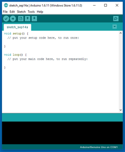
Now that the hardware is ready, it's time to work on the Arduino code.
1. Download and install Arduino IDE latest version
You can find the latest version for Windows, Linux or MAC OSX on Arduino's website: https://www.arduino.cc/en/main/software
Download it for free, install it on your computer and launch it.
2. Adding the libraries
For this project I used Robert Eisele's amazing Nunchuk Arduino library! You can find more about it on his website:
https://www.xarg.org/2016/12/using-a-wii-nunchuk-with-arduino/
Download the library at https://github.com/infusion/Fritzing/tree/master/Wii-Nunchuk
Navigate to Sketch-> Include Library -> Manage Libraries... on your Arduino IDE for adding the library.
How does the library works?
Nunchuk library comes with a set of functions for reading controller's sensors:
- nunchuk_buttonZ(): returns 1 if Z button is pressed, or 0 if it isn't;
- nunchuk_buttonC(): returns 1 if C button is pressed, or 0 if it isn't;
- nunchuk_joystickX(): returns x value of the joystick (between -127 and 127);
- nunchuk_joystickY(): returns y value of the joystick (between -127 and 127);
- nunchuk_pitch(): returns the angle of the controller in radians (between -180º and 180º);
- nunchuk_roll(): returns the roll angle of the controller in radians (between -180º and 180º).
The angles are returned in radians. I converted those values to degrees in my Arduino code.
Step 12: Arduino Code


Download Arduino's sketch file.
Plug the USB cable on your computer's USB port and upload the code. Uploading the code takes some time. You can use that time to give a 'like' and 'share' this tutorial while you wait! :D
After the upload was complete, unplug the USB cable, connect the power supply and turn on the power button. The code will start running imediatly.
Warning: when the code starts running, the robotic arm will move really fast to it's initial position. Be careful not to get hurt or damage nearby equipment during startup!
You'll possibly have to replace the starting angle of each servomotor depending on how your servos where mounted.
Code explained:
Before the setup, the code imports the libraries used on the sketch (nunchuk.h, wire.h and servo.h).
Pins to be used are defined, and global variables are declared. The angle# integer variables store the initial position for each servo. If you want your robot to start at a different position, change the values on those variables.
servo#_speed variables define the speed of the movement of each servo. If you want a specific servo to move faster, increase its value. angle#min and angle#max variables are used to limit the maximun and minimun angle for each servo. You can set those variables in order to avoid colisions between consecutive joints of the robot.
//Include libraries
#include <nunchuk.h>
#include <wire.h>
#include <servo.h>

//define variables
#define SERV1 8    //servo 1 on digital port 8
#define SERV2 9    //servo 2 on digital port 9
#define SERV3 10   //servo 3 on digital port 10
#define SERV4 11   //servo 4 on digital port 11
#define SERV5 12   //servo 5 on digital port 12
#define SERV6 13   //servo 6 on digital port 13

Servo s1; //servo 1
Servo s2; //servo 2
Servo s3; //servo 3
Servo s4; //servo 4
Servo s5; //servo 5
Servo s6; //servo 6

//define starting angle for each servo
//choose a safe position to start from
//it will try to move instantaniously to that position when powered up!
//those angles will depend on the angle of each servo during the assemble
int angle1 = 90; //servo 1 current angle
int angle2 = 30; //servo 2 current angle
int angle3 = 0;  //servo 3 current angle
int angle4 = 90; //servo 4 current angle
int angle5 = 90; //servo 5 current angle
int angle6 = 45; //servo 6 current angle
int servo1_speed = 3; //servo 1 speed
int servo2_speed = 3; //servo 2 speed
int servo3_speed = 3; //servo 3 speed
int servo4_speed = 1; //servo 4 speed
int servo5_speed = 1; //servo 5 speed

//define restrictions for each servo
//those angles will depend on the angle of each servo during the assemble
int angle1min = 0;   //servo 1 minimum angle
int angle1max = 180; //servo 1 maximum angle
int angle2min = 0;   //servo 2 minimum angle
int angle2max = 180; //servo 2 maximum angle
int angle3min = 0;   //servo 3 minimum angle
int angle3max = 180; //servo 3 maximum angle
int angle4min = 0;   //servo 4 minimum angle
int angle4max = 180; //servo 4 maximum angle
int angle5min = 0;   //servo 5 minimum angle
int angle5max = 180; //servo 5 maximum angle
int angle6min = 0;   //servo 6 minimum angle
int angle6max = 180; //servo 6 maximum angle

boolean display_angles = true; //boolean used to update the angle of each servo on Serial Monitor
During the setup, each servo is attached to an especific pin, and its position is started.
Serial communication (to Serial monitor) and I2C communication with the Nunchuk are also started here.
//SETUP

void setup() {
    //attach each servo to a pin and start its position
    s1.attach(SERV1);
    s1.write(angle1);
    s2.attach(SERV2);
    s2.write(angle2);
    s3.attach(SERV3);
    s3.write(angle3);
    s4.attach(SERV4);
    s4.write(angle4);
    s5.attach(SERV5);
    s5.write(angle5);
    s6.attach(SERV6);
    s6.write(angle6);

    //start serial communication
    Serial.begin(9600);

    //start Nunchuk
    Wire.begin();
    nunchuk_init();
}
The main loop is repeated over and over. Nunchuk status is read at each cycle. Depending on the readings, different commands are performed.
void loop() {

    //read Nunchuk sensors
    if (nunchuk_read()) {
        int x = nunchuk_joystickX();    //joystick X position
        int y = nunchuk_joystickY();    //joystick Y position
        boolean z = nunchuk_buttonZ();  //z button status
        boolean c = nunchuk_buttonC();  //c button status
        float pitch = nunchuk_pitch();  //pitch angle
        float roll = nunchuk_roll();    //roll angle
Joystick X will be used to move the servo #1.
The following block of code was used. First it checks if the value of the joystick is large enough. This way, noise and small variations are disregarded. If the value meet the requirements, the angle of the servo will be increased/decreased at a given speed.
//Turn left/right (at a fixed speed)
        //Turn left
        if (x > 90) {
          angle1 -= servo1_speed;
          display_angles = true;
          if (angle1 < angle1min) {
            angle1 = angle1min;
          }
        }
        //Turn right
        if (x < -90) {
          angle1 += servo1_speed;
          display_angles = true;
          if (angle1 > angle1max) {
            angle1 = angle1max;
          }
        }
        s1.write(angle1); //update servo position
A similar block is used for joystick y. It's used for changing the angle of servo #3. Servo #2 is kept fixed in this code.
Rotation of the gripper is given by the roll and pitch angles of the controller, measured by it's accelerometer. In order to make the control of the arm easier, the angle of the gripper is only updated when C or Z buttons are pressed.
When only C button is pressed, the code reads roll angle and use it as a set point. servo #5 is rotated until it reaches the set point. It's speed is proportional to the error between actual and desired position. A similar code is used for servo #4, which tracks Nunchuk's pitch angle.
// Enable accelerometer only when the buttons are pressed
        // Rotate gripper (only Z button pressed)
        if (c && !z) {
          roll = roll * 57.0 + 90.0; //convert do degrees
          servo5_speed = abs(angle5 - roll)/10 + 1; //speed proportional do the error between actual and desired angle
          if (roll > angle5) {
            angle5 += servo5_speed;
            display_angles = true;
          }
          if (roll < angle5) {
            angle5 -=servo5_speed;
            display_angles = true;
          }
          s5.write(angle5); //update servo position
        }
The gripper is closed whenever both C and Z buttons are pressed. When any of those buttons is released, the robot will open its gripper.
//Open/close gripper (both buttons pressed)
      if(z && c) {
        s6.write(90); //close gripper
        display_angles = true;
      }
      else {
        s6.write(45); //open gripper
      }
There's a block of code by the end of the sketch. It will display on the Serial Monitor the actual angle of each servomotor. It might be helpfull for choosing the starting angle of each motor.
Attachments

Step 13: Usage


Now that everything is ready, power up the robot and have fun!
The Nunchuk is used to control the five movements shown in the pictures: right/left rotation, up/down movement, gripper rotation, gripper up/down movement, and gripper open/close movements. You can combine those movements for perfoming different tasks.
You can modify the code for having different movements based on a combination of the buttons and angles of the joystick.
Step 14: Final Considerations
If you still don't follow my tutorials, take a look at those other projects in which I explain a little bit about internet of things, robotics and 3D printing. I hope you enjoy them too!
https://www.instructables.com/id/IoT-Wallet-smart-...
https://www.instructables.com/id/IoT-Air-Freshner-...
https://www.instructables.com/id/Minimalist-IoT-Cl...
https://www.instructables.com/id/IoT-Air-Freshner-...
https://www.instructables.com/id/Nunchuk-Controll...
Liked any of my projects? Please consider supporting my future projects with a small Bitcoin donation! :D
BTC Deposit Address: 1FiWFYSjRaL7sLdr5wr6h86QkMA6pQxkXJ

Participated in the
Epilog Challenge 9


