

Introduction: Basic Ciruitry


This lesson ifs for those who do not yet know basic electronics. This is the first in a tutorial series that will help in teaching people, bottom up, how to master electronics and manipulate it to their hearts' content.
This lesson will be discussing the following: What is a circuit?
Step 1: What Is a Circuit?

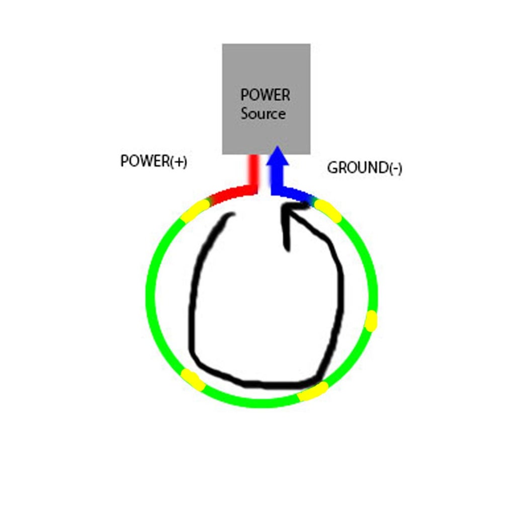
A circuit is a fully attached pathway for electrons to flow. The diagram above shows a complete circuit, which has a power source, ground and power, and something to connect the two end.
In the diagram above, the grey rectangle represents a power source, like a battery or a plug. This supplies the power you need to have your circuit run. Extruding from the power source are two terminals. The red end is power, and the blue end is ground. The green is the wire connecting these two ends. In a completed circuit, the positive energy from the power flows through the conductor (a fancy name for the green wire in the diagram, which in general is usually some kind of metal) into the ground.
Step 2: The Interface for Circuit Construction


In the first diagram above shows a diagram of a breadboard. In the image, you can see that paths on the bread board are marked in red, green and blue.
Keeping the same code from the previous diagram, the horizontal red and blue paths represent the power and ground. The vertical paths represent the parts of the circuit you connect between ground and power. On an actual breadboard, no visible paths will be visible, only a bunch of small holes, as seen in the second diagram.
You may notice, the grounds and powers are not connected. This isn't a completed circuit! What's going on?!
Step 3: Turning the Bread Board Into a Complete Circuit

When making a circuit on your breadboard, you first need a battery to attach to your power and ground. On your battery, it will usually indicate which end is positive or negative. Make sure you do not switch the ends, or else it will cause something called a short circuit*. Afterwards, you connect your power row, using a separate wire, to one of the vertical green labeled columns. For those who want to go crazy, use a second wire and connect one end on the first column and attach to a hole on a separate column. Repeat those steps to your own content. When you want to end a circuit, connect a final wire from the current column to the ground row that is connected to a battery. Then you have a complete circuit. Pointless, but complete.
*A circuit that directly connects ground and power. These are very dangerous, and cause electrical fires.-
Step 4: A Circuit Diagram of What You Made.
Again, all the same color coding, except yellow is the wire you used to connect power to conductor to conductor to ground.
Step 5: Using a Circuit to Influence the Physical World

Now you are going to build a circuit that will light up an LED. Do all of the same steps in the previous circuit except before you complete the circuit, take the led and connect it to two separate columns, as seen in the diagram. Then complete the circuit. The LED should light up*.
*The LED has one longer leg than another. Connect the longer leg closer to the power and the shorter leg to the ground. Otherwise it will burn out, and you, believe me, do not want that. It smells bad.
Step 6: What Your New Circuit Looks Like

This is the circuit from the previous slide in terms of a circuit diagram. Again, it is a regular complete circuit, except that you are using an LED to connect the conductor. By completing the circuit, electricity is running through the LED, hence turning it on.
Step 7: AND NOW...
You have officially entered the beginning of electronics. Next time on the chronicles of electonics, we will delve into the world of Arduino!
See you soon!


