

Introduction: TV Commercial Volume Suppressor

My dad constantly whines about how annoying it is when commercials are considerably louder than their accompanying program. Since his complaining was becoming more annoying than the actual commercials, I decided to create a little gadget that would solve both problems simultaneously. The gizmo I created will automatically lower the volume of the TV when it gets too loud, and can be programmed to work on any device that uses an IR based remote control.
Step 1: Components and Tools

Tools and Materials
- Soldering iron
- Solder
- Breadboard
- Hook-up wire
Components
- 1x 16x2 LCD screen
- 1x Arduino Nano (I used a cheap clone from Ebay)
- 3x 12mm momentary push buttons
- 1x Electret Microphone Breakout. Sparkfun. Adafruit.
- 1x trimpot
- 1x PN2222 transistor
- 1x TSOP38238 IR Receiver
- 1x IR LED
- 1x 100 ohm resistor
- 1x 220 ohm resistor
Step 2: Wire It Up

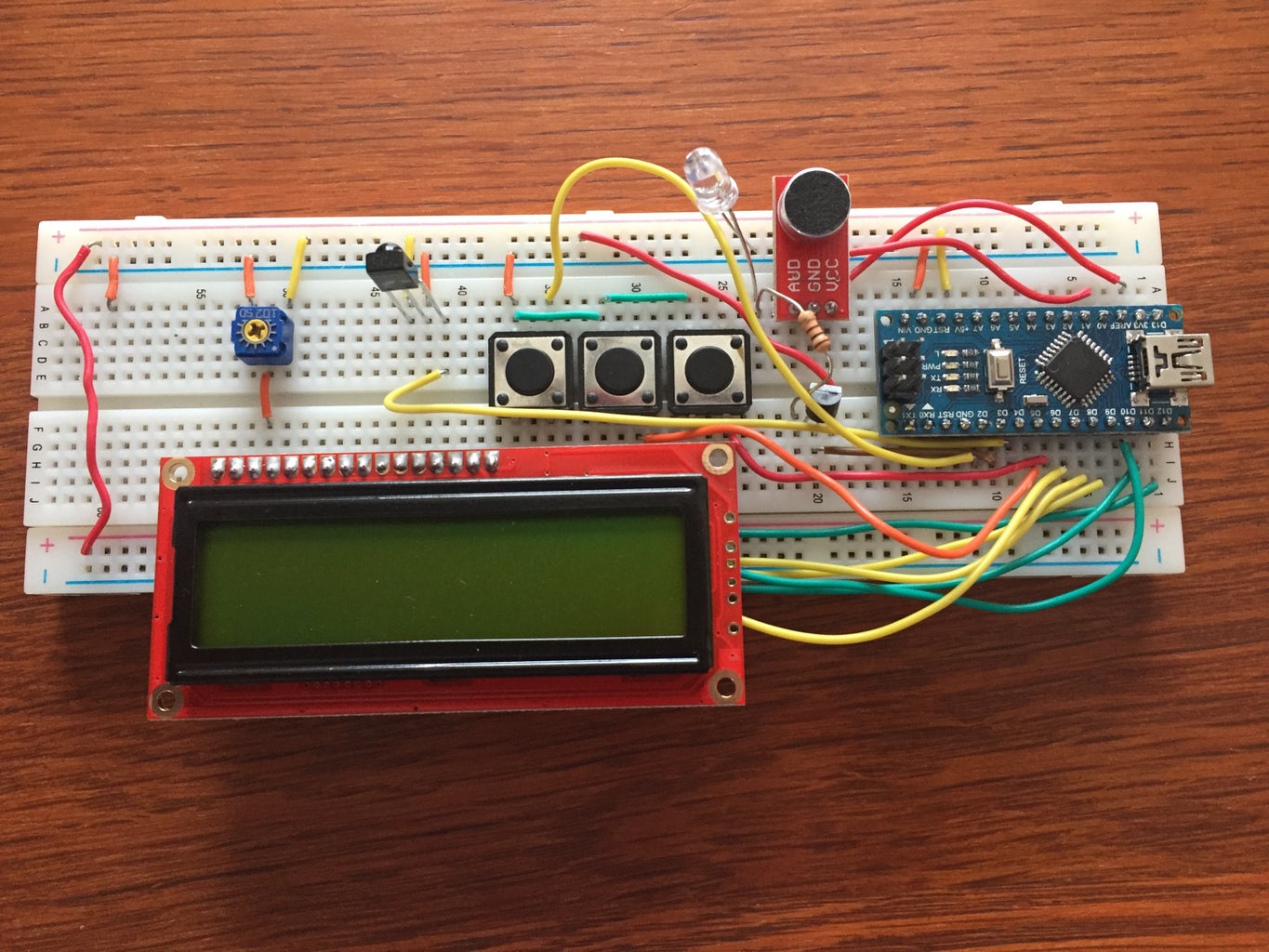


Since I was gifting this to my dad and wanted it to look nice, I decided to have a PCB professionally made. I used Eagle to create the schematic and board. My breadboard was looking pretty messy, so I would just use the schematic to guide your hook-up process. Here is a brief summary of the pinout.
- A0 goes to the microphone output
- Pin 2 goes to "Program" button
- Pin 3 goes to the transistor gate
- Pin 4 goes to the IR Receiver output
- Pin 5 goes to "Down" button
- Pin 6 goes to "Up" button
- Pins 7, 8, 9, 10, 11, and 12 go the the LCD.
- Put 3.3 volts across the microphone
- Put 5 volts across the transistor/IR LED, potentiometer, and LCD.

Step 3: How to Use It


The heavy lifting part of the code was actually borrowed from other things I found online. I used an IR library to both decode the TV remote's signals and to repeat the signal to the TV. I also borrowed another snippet of code to accurately measure the reference voltage of the Arduino's ADC since even small errors would make large difference in the microphone's volume readings. Don't ask me how they work, because it is beyond me. I just figured out how to use them through trial-and-error.
Basically, the Arduino constantly checks the state of the three buttons and the volume. If either of the Up or Down buttons are pressed, the volume threshold, or maximum volume before the system is triggered to decrease the TV's volume, will be raised or lowered. To set the IR Code that is sent when the threshold is exceeded, press the Program button and followed by the Up button. When the screen prompts you to press the -Volume button, aim your TV's remote at the IR receiver and press the -Volume button until the screen shows you a hexadecimal value that corresponds to your TV's -Volume command. (I added that as a sanity check). It sometimes takes a few tries to get it to work, I'm not sure why though.
If the volume is measured to be above the threshold, the Arduino will send out the -Volume command. You can change the "burst length", or how many -Volume commands are sent when the threshold is exceeded, by pressing the Program button, then the Down button. The screen will show you the current burst length, which can be changed using the Up and Down buttons and then saved by pressing the Program button again.
All of this information is stored in the EEPROM so that the system remembers your presets even when you unplug it.
As another sanity test, the Arduino will send out a -Volume command every time it starts up. This way, you can just press the Arduino's reset button to test whether or not the device is working.
Step 4: Test It
It works!
Step 5: Put It All Together


Once I confirmed it worked, I ordered the PCB and then soldered everything on to it. I also used my university's laser cutters to make a little MDF box to house it, but these are both extra steps that aren't completely necessary. Once these were done, the project was complete! I put all of this together during finals week and may have neglected some details, so let me know if I missed anything!
Step 6: Errors
I added this extra step as an appendix. Since this was my first time using Eagle and making a PCB, I ended up making a couple of errors.
First: Since I used a clone of the Arduino Nano, the PCB actually has four extra pins for the controller. However, the board still works so long as you solder the controller to the right pins.
Second: The potentiometer that came with the LCD didn't match the one I used to design the board. You can bend the wires to make it fit, but it doesn't look as nice or feel as secure if the right pot had been used.
There are also a few things I would do differently in the future. First, if I had used an LCD with a backlight, I would have added a way to cut power to the LCD after the screen hadn't been updated in a while to save power. Second, you might be able to actually remove or reduce the 100 ohm resistor in front of the IR LED to make it brighter. Since the LED is only on for short bursts it probably wouldn't burn out. However, I have yet to test this. I also recommend using a microphone with an adjustable gain. I used the Sparkfun microphone and it wasn't as sensitive as I would have liked.

Second Prize in the
Remote Control Contest 2017

Participated in the
Arduino Contest 2017

Participated in the
Epilog Challenge 9


