

Introduction: DIY Word Clock


Today, I will show you how to build a Word Clock. It is basically a clock which displays time using words. I will also show you how to use a Shift Register and RTC using a microcontroller. Shift Register can come in very handy if you run out of pins in a microcontroller, so its a good thing to learn about them.
Wait no more and get right into it.
Step 1: Watch the Video!
The video has the detailed explanation of all the steps involved in the build. So watch it first to get a better grasp of the project.
Step 2: Get the Parts Required.

Arduino:
INDIA - http://amzn.to/2FAOfxM
US - http://amzn.to/2FAOfxM
UK - http://amzn.to/2FAOfxM
74HC595 Shift Register:
INDIA: https://amzn.to/2pGA8MD
US: https://amzn.to/2pGA8MD
UK: https://amzn.to/2pGA8MD
DS3231 RTC:
INDIA: https://amzn.to/2pGTxh4
US: https://amzn.to/2pGTxh4
UK: https://amzn.to/2pGTxh4
ULN2803 Darlington Transistor Array:
INDIA: https://amzn.to/2GculoX
US: https://amzn.to/2GculoX
UK: https://amzn.to/2GculoX
Step 3: Test the Shift Register.


There are four kinds of shift register – Serial In Parallel Out (SIPO), SISO, PISO, and PIPO.
We are going to use 74HC595 which is an 8 bit SIPO shift register that means it will take 8 bit serial data, and convert it into 8 bit parallel data. You might wonder why we need a shift register. Let’s see. An Uno has 14 digital I/O pins and 6 analog input pins. Even after combining them we only have 20 number of pins, out of which not all are output capable. And that is the problem because we will be working with a lot of LEDs in this project.
A shift register consumes very less pins of the microcontroller, 3 in this specific case, and can control a large number of LEDs with it, which is 8 in this case. And that’s not it. This shift register can also be daisy chained with another shift register to control even more LEDs, and the second one can be daisy chained with the next shift register and so on. What I’m trying to say is just by using three pins, you can control lots and lots of digital devices.
See pin diagram of the Shift register. Pin number 1 through 7 along with pin 15 is the parallel output data.
Like all 74 series ICs, 8 and 16 are power pins.
Pin 14 - aka serial input, Pin 12 - aka latch, Pin 11 - aka clock, are the control pins I talked about.
Pin 10 is called serial clear, and is used to clear the output of shift register, will be held high throughout the project; pin 13 called output enable, as the name implies, enables the output, will be held held low.
Pin 9 is used for daisy chaining and is connected to next 74595.
Let's see the working. The latch is pulled down before sending the serial data. Then each of the 8 bits is sent one by one. The shift register determines that new data is coming by checking the status of the clock pin, if clock pin is high, the data is new. When all the bits are completely sent, the latch is pulled high to actually reflect the data in the 8 output pins.
To execute all of this in Arduino IDE, there is a function called shift out having four parameters (see picture). The first two are self-explaining, fourth one is the 8 bit serial data, written in binary format here. If the third parameter is MSB first, then the MSB of the serial data will be sent first and will actually be reflected in the pin 'Qh' of the register preceding the remaining data and if the third parameter is LSB first, the LSB will be shown in the pin 'Qh'.
Now the current output capability of this shift register is only 20 mA per pin, and we will be needing more than that, that’s where ULN2803 comes in.
If you want to test the functioning of the shift register, I have attached a sketch in this sketch along with the pictures, just apply power, connect pin 11, 12 and 14 to any digital pins of Arduino and upload the sketch. See the video for better understanding.
Attachments

Step 4: Set the Date and Time of RTC.
I connected the RTC to Arduino like any other I2C device (SDA to A4 and SCL to A5), and applied power. Then I opened the sketch attached in this step and set the parameters of the "setDS3231time" by referring the commented line just above it, to set the correct date and time of the RTC. Then I uncommented that line and uploaded the program to Arduino. Without disconnecting anything, I commented the line back again and uploaded the sketch to Arduino. Now remove power from the RTC, leave it for a minute or two, connect it to Arduino once again, and open serial monitor. If the date and time displayed on the monitor is correct, you know that the RTC is working fine.
Attachments
Step 5: Make the Circuit Board.


The connection diagram is attached in this step. You can either hand solder it or order a PCB. It's all up to you. I ordered PCB as I have once hand soldered the PCB, and it was quite time taking and the bottom was really clumsy too.
I ordered my PCB from JLCPCB.
Link for schematic and PCB: https://easyeda.com/Tesalex/Word_Clock_copy-c7c7a7...
Step 6: Prepare the LEDs.


1. Check all the LEDs with a 3V battery.
2. Chop off the top of the LED.
3. Shorten one leg of resistor and anode (longer leg) of LED.
4. Solder the short leg of resistor and the anode together.
Do this to all the LEDs you are going to use.
Step 7: Build the Backbone and Final Test.


After LEDs are done, I took a cardboard from an appliance packaging, 8x8 inch in size.
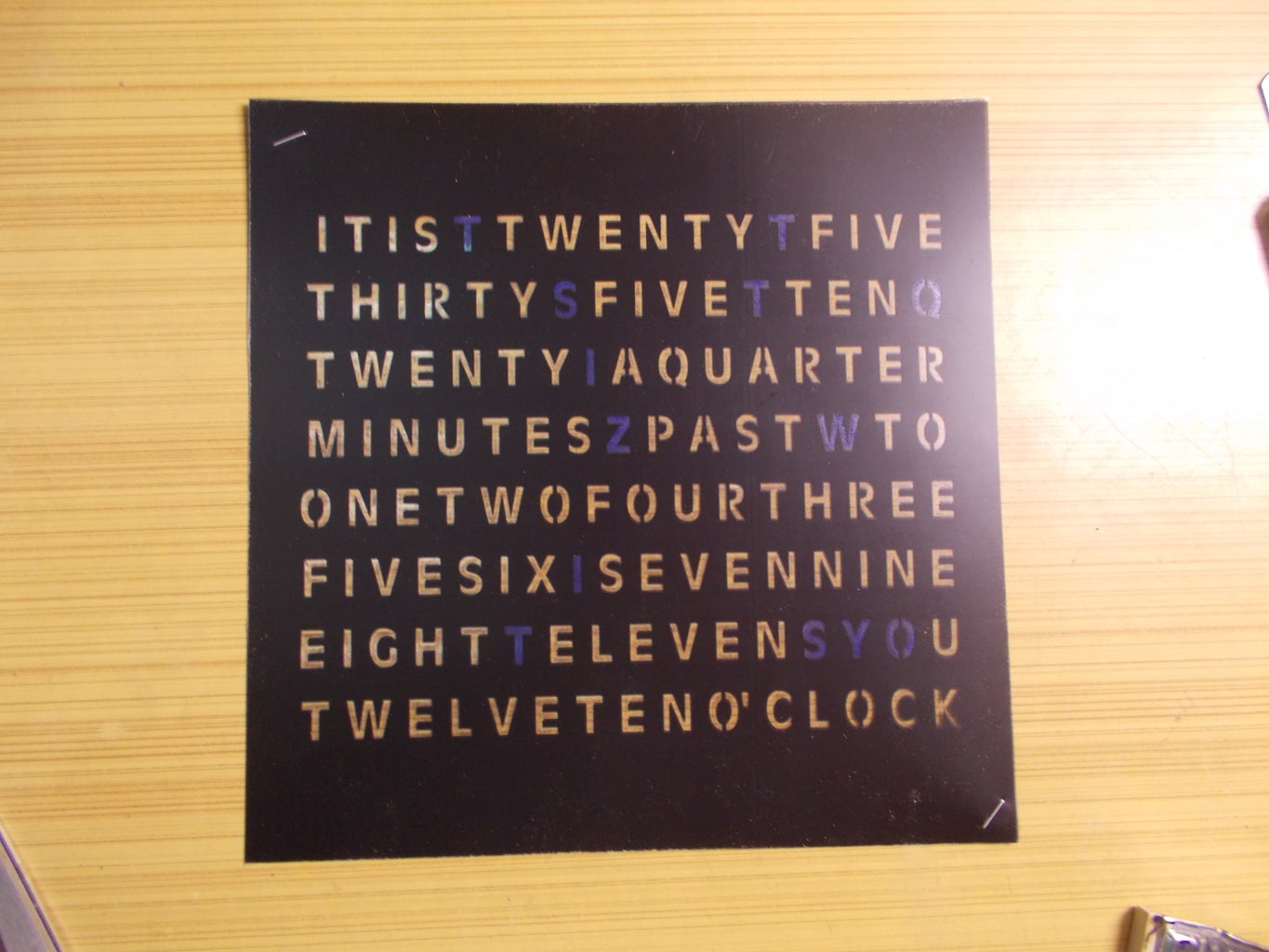
I printed the template attached t this step on a white paper and two copies on a transparent sheet, as the ink is a bit light.
Now I cut the template to actual size and stick it on the cardboard using some glue. After this, I made holes for the LEDs according to the length of the words so that they do not look dim when LEDs glow. Then I took 4 solid copper wires and stick them between two rows of LEDs. Then I pushed the LEDs in the holes keeping the resistor led close to the copper wire. After this, I soldered the resistor to the copper wire and soldered the cathode of LEDs of the same word together. Then I chopped off excess leads.
Now I took three ribbon cables having eight wires each and on one end, I soldered male headers and other end will be soldered to LEDs. These headers will then go the female headers of the PCB. But which wire will be soldered to what word? Attached with this step is the sequence of the headers connection according to the program I have written. Therefore, first wire of header 1 should go to the word twenty five, second to thirty, first wire of second header to one and so on.
Now you will notice that the last 4 headers are not connected to anything and you might notice that the copper wire at the back must be soldered to 5 Volts. So, I shorted them all out and connected them to the very last header and if you remember also connected the last female header to Vcc or 5 Volts. The word “it is” and “o’clock” must be on always therefore I soldered them to second last pin of the header and on the PCB I grounded them. Lastly, the “minutes” word is not always on, and needs controlling too, so I soldered it to the fifth pin of third header, and the reason why we shorted pin 3 to fifth female header while assembling the PCB as pin 3 controls the word minute in the program I have written.
That being said, it is now time to check the functioning by connecting the headers at their respective places, uploading the sketch to Arduino and applying 5 volts and mine is working great. I quickly soldered a DC barrel connector to the power pins as I’ll be using a 5 volt adapter, otherwise I would have used the 7805, for which I have already left a space in the PCB.


Step 8: Remove the Light Bleeding.


For removing the light bleeding to other words I used a 1 cm height cardboard piece and stick it using some hot glue between every word. I started from the center then came all the way out. After this I measured and cut the cardboard for each place and then stick it again using two drops hot glue.
Step 9: Put Everything in the Enclosure.


I made an enclosure out of a 12 mm MDF having internal dimensions 8x8 inch and made sure that the cardboard fits in perfectly. I also cut an acrylic sheet of the fitting size and keep in mind that this time, it must not be much thick. I attached the acrylic sheet and also made a hole for the barrel jack on one side of the enclosure.
Now I brought each of the vinyl to size by removing the corners and afterwards stacked them together and stapled them on two opposite sides. On the back of the vinyl, I stick and opaque tape to the words which were of no use.
Then I dropped the vinyl to the enclosure and also the cardboard I have prepared and powered it, and everything looks great.
I cut a piece of cardboard from corners so that it is easy to remove them if required.
Few changes (not really necessary):
I changed the power wire to a thicker gauge so that it can carry the current required with ease and also connected the RTC using a female header (recommended) as it sometimes require to change the date and time. You can add hot glue to hold the cardboard in place if required, but mine has enough friction to just be there even in an earthquake.
Step 10: Done.

I hope you learned something today. Feel free to share your thoughts and tips about the project and consider subscribing on Instructables and to our YouTube channel.
Enjoy your creation :)


