

Introduction: Arduino LiPo Battery Watcher


With the Help of 2 Arduinos, too low LiPo Batteries will never be a problem again.
I made this project for this particular reason:
Many people can't view their LiPo-Battery-Volatage, bacause their Radio for the RC-Stuff hasn't got telemetry or can't handle such high voltages.
Step 1: Let's Connect the Speaker to Your Receiver.

First, connect some piezoelectric speaker to your Arduino, in my case it's an Arduino UNO.
- > GND
+ > Any PWM Pin you like, be careful when programming.
Step 2: Connect the 433 MHz Receiver-Module to Your Arduino.
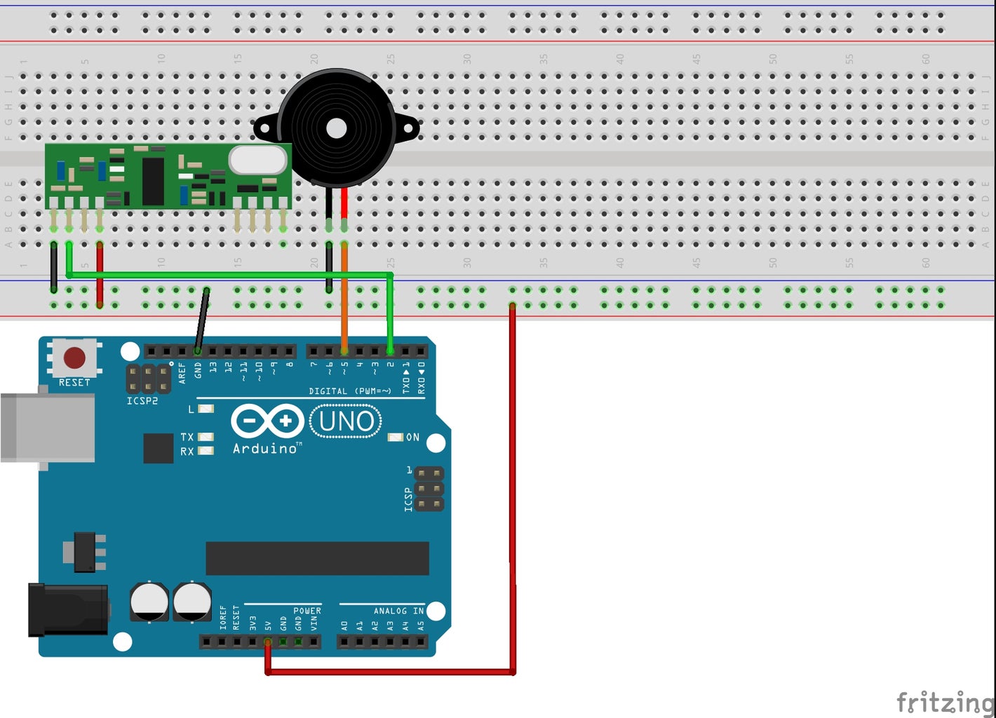
Be sure to connect the DATA-Pin to Pin #2, that's Interrupt #0 on your Arduino UNO.
GND > GND
VCC > 5v
DATA > Pin 2
Most Receiver-Units today come with only 4 Pins, unlike in the picture.
Connect these the same way as above.
Step 3: Connect the 433 MHz Transmitter-Module to Your Transmitting Arduino.

GND > GND
VCC > 5v
DATA > Any pin you like, be careful to choose the right pin when programming.
Step 4: Connect 2 Wires to Your Transmitting Arduino.
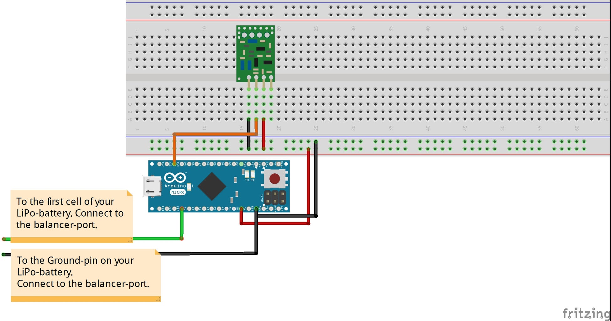
The first wire goes from the GND Pin of your Arduino to the Ground of the balancer-Connection on your LiPo-Battery.
The second one goes from any Analog Input Pin of your Arduino to the first cell on your balancer-port on your LiPo-Battery.
DO NOT connect this wire to any other cell on your LiPo-Battery then to the first one!
Step 5: Give the Transmitting Arduino Some Power.

Because the voltage-regulator on the original Arduino MICRO isn't the best one you can get, the Arduino MICRO will read some wrong values out of your LiPo-Battery.
Therefore, the Arduino MICRO gets it's power from an external, 5 Volt UBEC.
If you're a bit into that kind of RC-Stuff, you will know what a UBEC is.
If not, just google it.
Basically, it's a power regulator that converts, for example, 5 - 20 Volts to constantly 5v.
+ 5v from UBEC > +5v on your Arduino MICRO
- from UBEC > GND on your Arduino MICRO
When you're using an Arduino UNO, you can connect voltages anywhere between 7 - max. 20 Volts directly on your Vin Pin on your Arduino UNO.
Ground goes to GND.
Step 6: Add Coil Loaded Antennas to Your 433 RF-Modules.

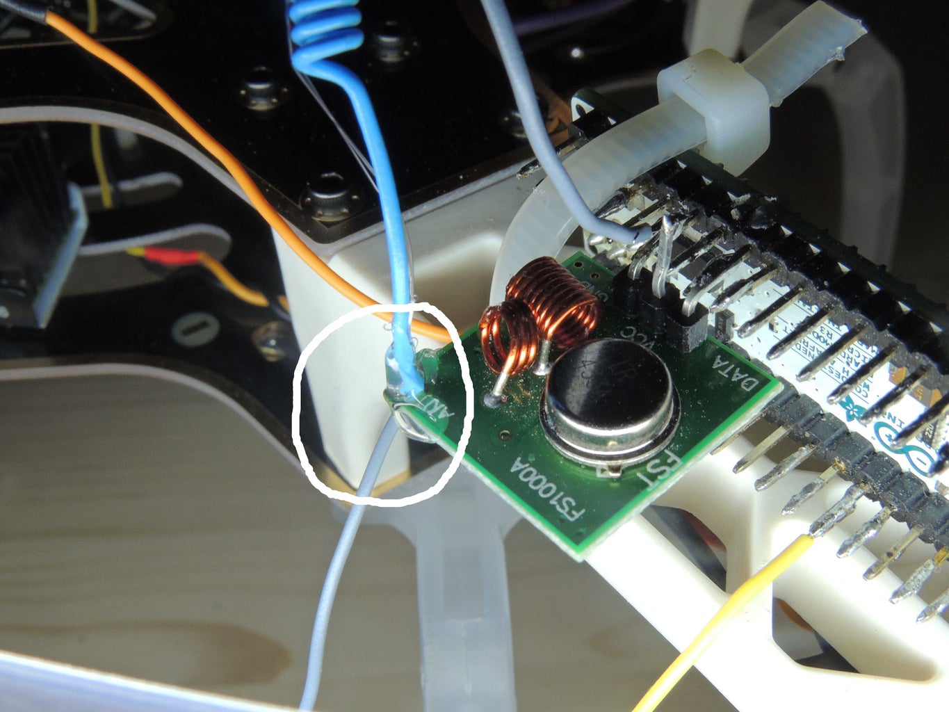
The Antenna should look like in the images above.
Solder them onto the ANT-Connection directly to the PCB of the RF-Modules.
You will notice. that you'll get WAAAAY more range out of these small electronic parts!
Do the same thing on both your transmitter and your receiver modules.
Step 7: Give the Receiving Arduino Something to Eat
Take a battery, 7 - max. 20 Volts, and connect it to your Arduino UNO.
+ of your battery > Vin Pin on Arduino UNO
- of your battery > GND on your Arduino UNO
A switch probably wouldn't be bad, either... ;)
Step 8: Program the Transmitter.

You can find the scetch on codebender.cc.
Step 9: Program the Receiver-unit.

You can find the sketch on codebender.cc.
Step 10: Mount the Transmitter on Your RC-Stuff and Enjoy ;)
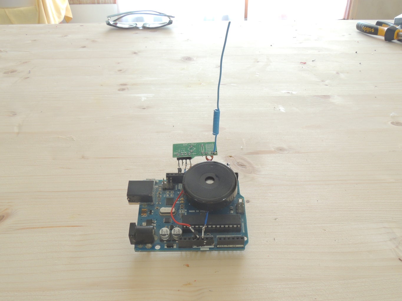
You have sucessfully build your LiPo-Watcher.
Now, you can take this one step further and add a LCD-Display, or all kind of stuff to it.
Don't forget to mount in onto your RC Multicopter/Plane/Car/Boat/...
In my case it's a Hexacopter.


