

Introduction: Arduino - Security Panel System With Using Keypad and LCD Display


In this tutorial we will learn how to make an Arduino Security Panel System with using Keypad and LCD Display.
We will be able to open the door by entering the correct password.
Step 1: Required Hardware
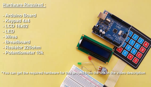
- Arduino Board - https://goo.gl/UyGYeF
- Keypad 4x4 - https://goo.gl/jtGlx5
- LCD 16x02 - https://goo.gl/8S27hc
- LED
- Wires - https://goo.gl/8S27hc / https://goo.gl/8S27hc
- Breadboard - https://goo.gl/8S27hc
- Resistor 220ohm
- Potentiometer 10k - https://goo.gl/8S27hc
- Recomended Site - https://goo.gl/3j489l
Step 2: LCD 16x02 Connection


The Arduino's +5V and GND will be connected to the pin of the breadboard
The LCD has 16 pins and the first one from left to right is the Ground (GND) pin
The second pin is the VCC which we connect the +5V pin on the breadboard.
Next is the Vo pin on which we can attach a potentiometer for the contrast of the display
The RS pin will be connected to the A0 pin of the Arduino.
The RW pin will be connected to the GND pin of the breadboard.
The E pin will be connected to the A1 pin of the Arduino.
The D4 pin will be connected to the A2 pin of the Arduino.
The D5 pin will be connected to the A3 pin of the Arduino.
The D6 pin will be connected to the A4 pin of the Arduino.
The D7 pin will be connected to the A5 pin of the Arduino.
The A (anode) pin will be connected to the +5V pin of the breadboard.
The K (cathode) pin will be connected to the GND pin of the breadboard.
The potentiometer's other pins will be connected to the +5V and GND pin of the breadboard.
Step 3: Keypad 4x4 and LED Connections

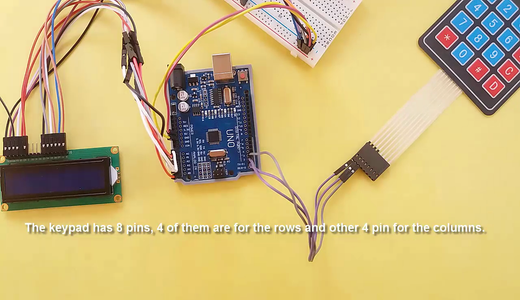
The keypad has 8 pins, 4 of them are for the rows and other 4 pin for the columns.
The keypad I'm using is 4x4. It has an additional connection input.
The keypad used in the circuit diagram is 3x4.
The Keypad's pins will be connected respectively to the Digital 1-2-3-4-5-6-7-8 pin of the Arduino.
The Red and Green LED will be attached on the breadboard
The 220 ohm resistor will be connected to the anode leg of the LED
The LED cathode leg will be connected to the GND of the breadboard.
The LED resistor leg will be connected to the Digital 10-11 of the Arduino.
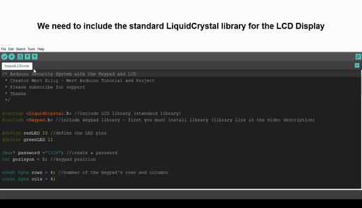
Step 4: Source Code

Get the source code - https://goo.gl/hfgIv3
We need to include the standard LiquidCrystal library for the LCD Display
The Keypad library needs to be additionally installed.
Get the Keypad Library - https://goo.gl/PUiBBA
Put the Keypad folder in "arduino\libraries\"
Then we need to define the LED pins
Define some variables needed for the program
Define the keys of the Keypad
Step 5: You Can Subscribe to My YouTube Channel

You can subscribe to the my YouTube channel for more tutorials and projects. Subscribe for support. Thank you.
Go to my YouTube Channel - https://goo.gl/f0RHmR


