

Introduction: Arduino - Balance - Balancing Robot | How to Make?


In this tutorial we will learn how to make Arduino balancing (balance) robot that balances itself. First you can look at the video tutorial above.
Step 1: Required Hardware
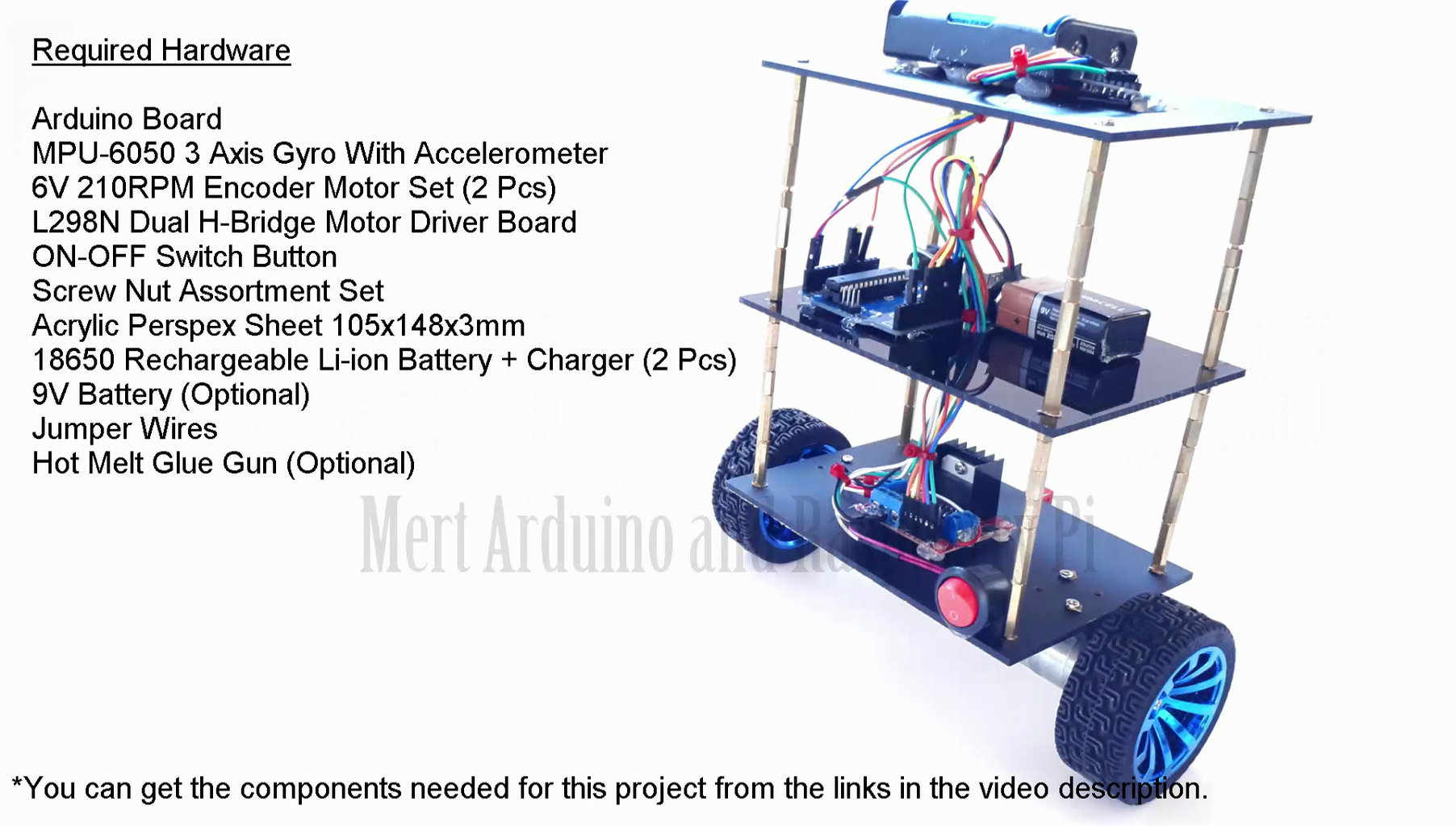
Arduino Board (Uno) -- http://bit.ly/2xt9MVk
MPU-6050 GY521 Acc+Gyro -- http://bit.ly/2swR0Xo
DC 6V 210RPM Encoder Gear Motor Set -- http://bit.ly/2squXlW
L298N Motor Driver -- http://bit.ly/2Ld6QOM
Switch Button -- http://bit.ly/2HbD3Ds
M3 Hex Threaded Spacer Screw Nut Set -- http://bit.ly/2sAcenp
Acrylic Perspex Sheet -- http://bit.ly/2kFg8rn
3.7v 18650 Rechargeable Li-ion+Charger -- http://bit.ly/2LNZQcl
9V Battery -- https://goo.gl/xaD6Tf
Jumper Wires -- http://bit.ly/2J6de9E
Hot Glue Gun -- https://goo.gl/2znyr6
Arduino Starter Kit and Supplies(Optional):
Arduino Board & SCM Supplies #01 -- http://bit.ly/2J2AFF7
Arduino Board & SCM Supplies #02 -- http://bit.ly/2Hb1NvD
Arduino Basic Learning Starter Kit #01 -- http://bit.ly/2sxyG0v
Arduino Basic Learning Starter Kit #02 -- http://bit.ly/2Lf5ToV
Arduino Basic Learning Starter Kit #03 -- https://amzn.to/2sqQ47X
Mega 2560 Starter Kit with Tutorial -- https://amzn.to/2Jkdtl7
Sensor Module Kit For Arduino #01 -- http://bit.ly/2JanxK7
Sensor Module Kit For Arduino #02 -- http://bit.ly/2J93QCg
Step 2: Assembly of the Robot


- Drill four corners of 3 Acrylic Sheets. (Image 1 and 2)
- Between each acrylic sheet will be about 8 cantimeters / 3.15 inch. (Image 3)
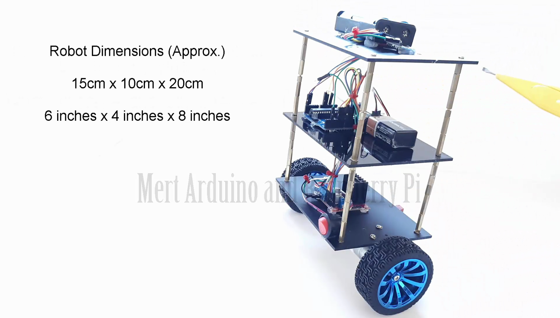
- Robot Dimensions (approx.) 15cm x 10 cm x 20cm. (Image 4)
- The DC motor and the wheels will be placed at the center (midline) of the robot. (Image 5)
- L298N Motor Driver will be placed in the first floor center (midline) of the robot. (Image 6)
- The Arduino board will be placed in the second floor of the robot.
- The MPU6050 module will be placed on the top floor of the robot. (Image 7)
Step 3: Connections


- Test the MPU6050 and make sure it works! Connect the MPU6050 tot the Arduino first and test the connection using the codes in the below tutorial. The daha should be displayed on the serial monitor.
Instructables Tutorial - MPU6050 GY521 6 Axis Accelerometer+Gyro
YouTube Tutorial - MPU6050 GY521 6 Axis Accelerometer + Gyro
- The L298N module can provide the +5V needed by the Arduino as long as its input voltage is +7 V or greater. However, I chose to have separate power source for the motor.
Step 4: How Does Balancing Work?
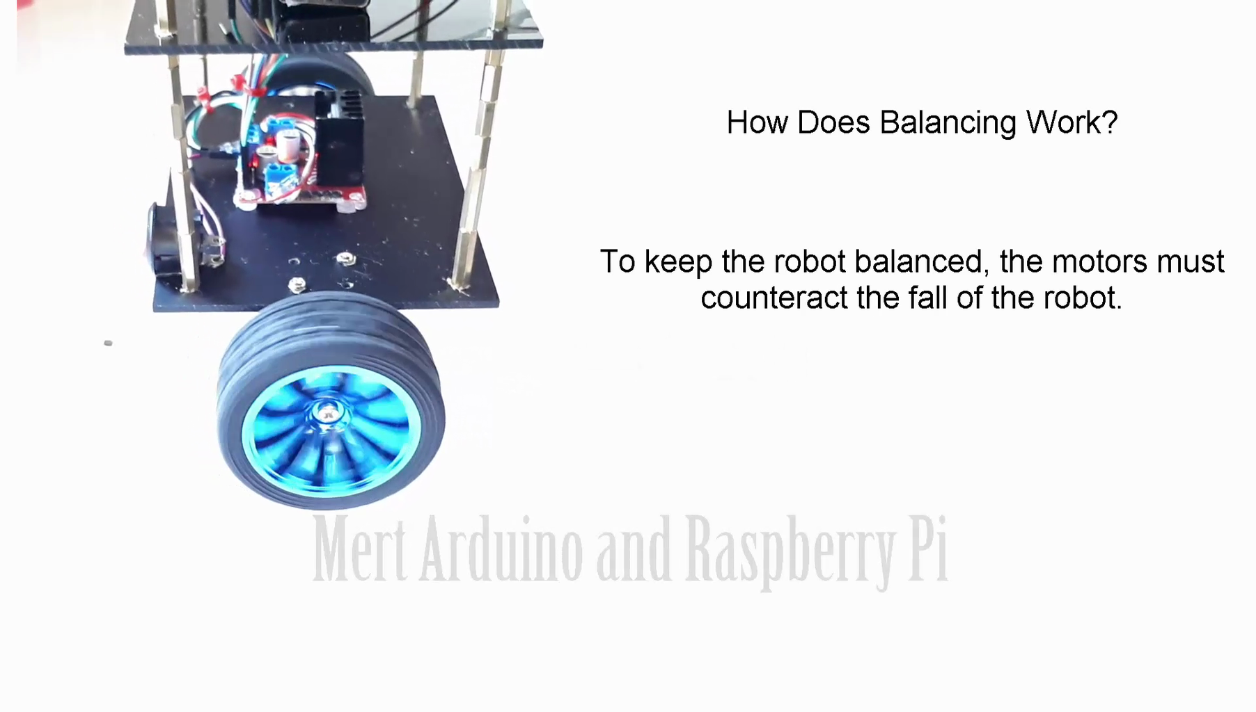
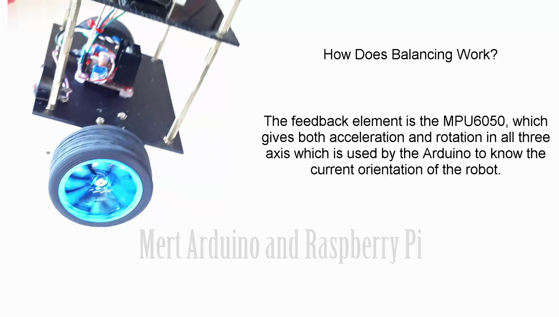
- To keep the robot balanced, the motors must counteract the fall of the robot.
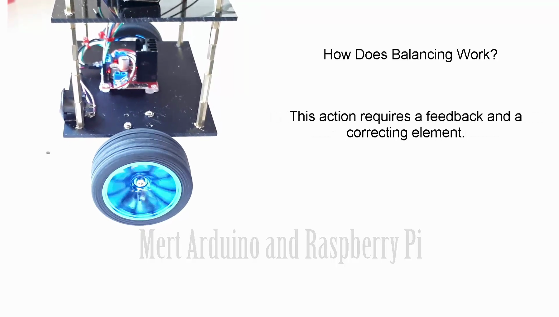
- This action requires a feedback and a correcting element.
- The feedback element is the MPU6050, which gives both acceleration and rotation in all three axis which is used by the Arduino to know the current orientation of the robot.
- The correcting element is the motor and wheel combination.
- The self-balancing robot is essentially an inverted pendulum.
- It can be balanced better if the center of mass is higher relative to the wheel axles.
- This is why I’ve placed the battery pack on top.
- The height of the robot, however, was chosen based on the availability of materials.
Step 5: Source Code and Libraries

The code developed for the balance robot is too complicated. But there is no need to worry. We will only change some data.
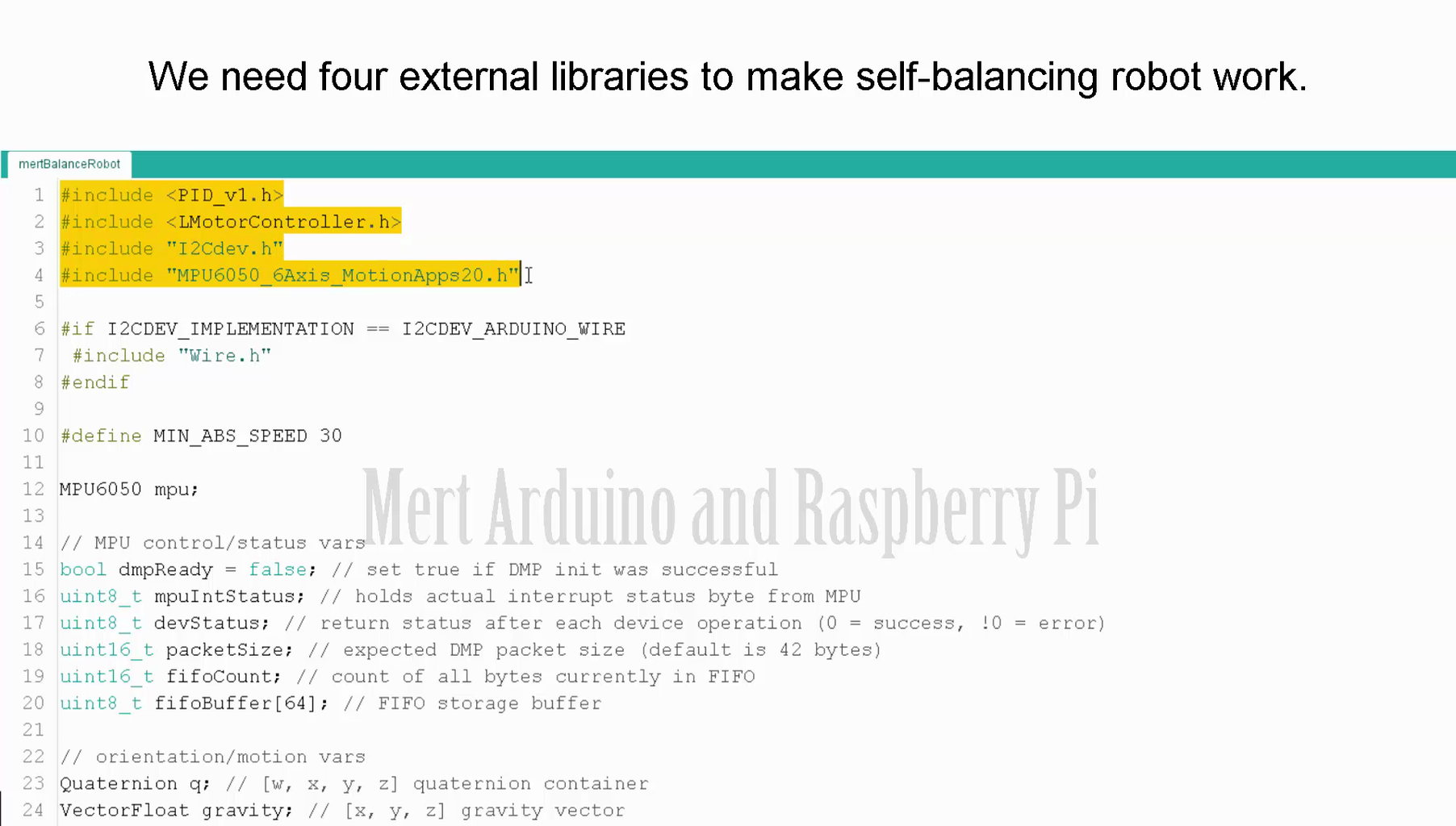
We need four external libraries to make self-balancing robot work.
- The PID library makes it easy to calculate the P, I, and D values.
- The LMotorController library is used for driving the two motors with the L298N module.
- The I2Cdev library and MPU6050_6_Axis_MotionApps20 library are for reading data from the MPU6050.
Download Libraries
PID -- https://goo.gl/gDHGoW
LMotorController -- https://goo.gl/gDHGoW
I2Cdev -- https://goo.gl/gDHGoW
MPU6050 -- https://goo.gl/gDHGoW
Get the Source Code - https://goo.gl/RR1XsJ
What is PID?
- In control theory, keeping some variable (in this case, the position of the robot) steady needs a special controller called a PID.
- P for proportional, I for integral, and D for derivative. Each of these parameters has “gains” normally called Kp, Ki, and Kd.
- PID provides correction between the desired value (or input) and the actual value (or output). The difference between the input and the output is called “error”.
- The PID controller reduces the error to the smallest value possible by continually adjusting the output.
- In our Arduino self-balancing robot, the input (which is the desired tilt, in degrees) is set by software.
- The MPU6050 reads the current tilt of the robot and feeds it to the PID algorithm which performs calculations to control the motor and keep the robot in the upright position.
PID requires that the gains Kp, Ki, and Kd values be “tuned” to optimal values.
We will adjust the PID values manually instead.
- Make Kp, Ki, and Kd equal to zero.
- Adjust Kp. Too little Kp will make the robot fall over (not enough correction). Too much Kp will make the robot go back and forth wildly. A good enough Kp will make the robot slightly go back and forth (or oscillate a little).
- Once the Kp is set, adjust Kd. A good Kd value will lessen the oscillations until the robot is almost steady. Also, the right amount of Kd will keep the robot standing even if pushed.
- Lastly, set the Ki. The robot will oscillate when turned on even if the Kp and Kd are set but will stabilize in time. The correct Ki value will shorten the time it takes for the robot to stabilize.
Suggestion for better results!
I recommend that you create a similar robot frame using the materials used in this project to make the source code for the Balance Robot work stably and efficiently.
Step 6: For Support

- You can subscribe to the my YouTube channel for more tutorials and projects.
- Also you can subscribe for support. Thank you.
Visit to my YouTube Channel - https://goo.gl/f0RHmR


