

Introduction: Arduino UNO Professor


Arduino has a lot of resources available on the Web. In the official website, www.arduino.cc we can find a lot of information, and most importantly, a free IDE interface for programming the microcontroller, nut before you buy an Arduino UNO, you need to know that you can simulate a lot of ideas just using the Autodesk Circuit.
The purpose of this Instructable, is to make a guide that allows the user to learn to simulate programming for Arduino UNO, through the Web application Autodesk Circuits, building a lot of examples that will guide them in learning to program I / O ports, serial communication between devices, electric motors and servomotors, 7-segment display, among others.
Step 1: Install the Application and Run to Start Familiar With It.
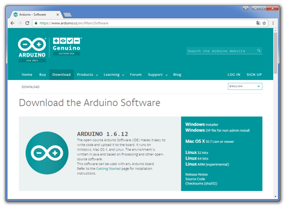
Go to the Download Section. (Clic on "View All Steps" to see the entire tutorial)
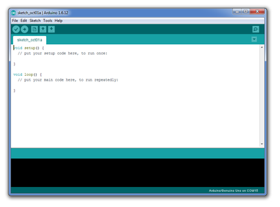
Step 2: Download and Install the Arduino IDE

Step 3: We Started to Make Programming Examples Based on an Arduino UNO R3, Like the One Shown in the Following Image:
Step 4: Image Arduino UNO R3
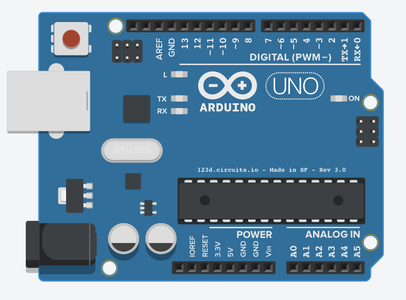
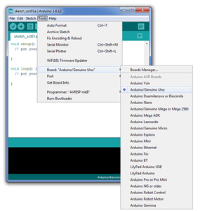
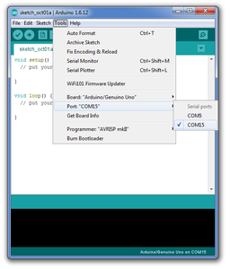
Normally when you connect the Arduino UNO R3 to the USB port on the computer, the software automatically recognizes it as a "Arduino / Genuine ONE". While it is recognizing the port in which you have connected.
Step 5: Autodesk Circuits
If all went well, you are ready to begin programming the Arduino UNO R3.
But it is possible to enter the world of programming with Arduino without an Arduino, thanks to Autodesk Circuits.
Let's see what this is about…!
Autodesk Circuits, It is a Web platform capable of simulating the operation of electronic circuits and even is capable to simulate a program loaded into a virtual “Arduino UNO”, running each program line, and showing the results of the programming that we make. You can register on this platform for free, and you can create your own designs easily, learning and modifying your programs the number of times you want it. To use this interesting tool, you must enter the following web address:
Now register your user and start designing your ideas:
Let's start by understanding how the simulator Autodesk Circuits works. In the next picture you can see how the Autodesk Web platform is:
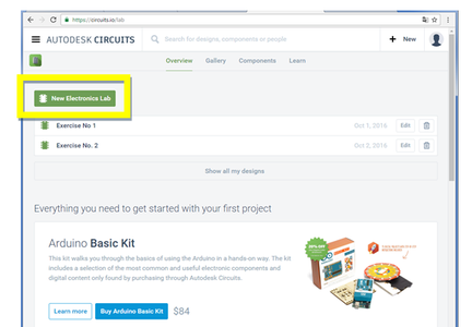
Step 6: Overview

In the section called "Overview", we can find the option to create a new project “New Electronics Lab”, and even we can see a list of projects already created, which you can edit when you want.
Step 7: Overview Menu:

If you want to start a new project, click "New Electronics Lab".
Step 8: Gallery Menu:

In the section called "Gallery", we can find a Variety of projects posted by other users. The interesting thing about this section is that we have access to the programming code each.
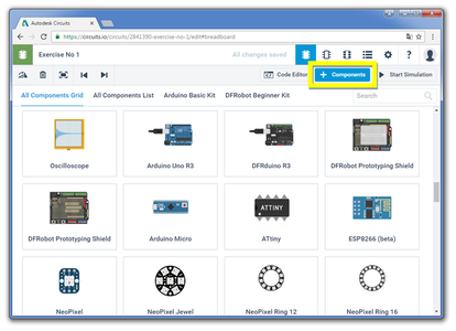
Step 9: Components Menu:


In the section called "Components" we can get a good variety of electronic components.
Step 10: Learn Menu:
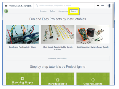
In this section are tutorials for learning about using "Autodesk Circuits".
You may get lots of examples, explanatory videos that will give you an idea of the advance knowledge relative to the Arduino programming.
Step 11: Start Working With Autodesk Circuits
Learn to perform basic circuits in order to understand programming as some of the devices available in the library.
The first step to advance this process will then start a new project, so clic on “New Electronics Lab”:
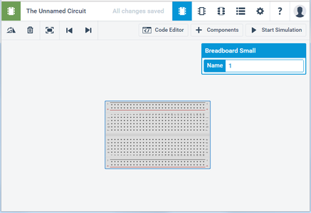
Step 12: Now You Can See an Empty Breadboard on Which We Can Work:

It is not necessary to use a breadboard so big to start with our projects, so we can resize the breadborad entering to the components Library, which we can get some other options.
Step 13: Firts Project
For this first project, I selected a small Breadboard and I deleted the Breadboard that Autodesk Circuits gives us to start a new project. To delete a component in our project, simply select it by clicking on it, and then click the trash icon.
Go back to the component library and select a Breadboard small.
Step 14: How to Make Connections Between Components, in Video:

Step 15: Now Try to Mount the Following Schematic Diagram on Breadboard:
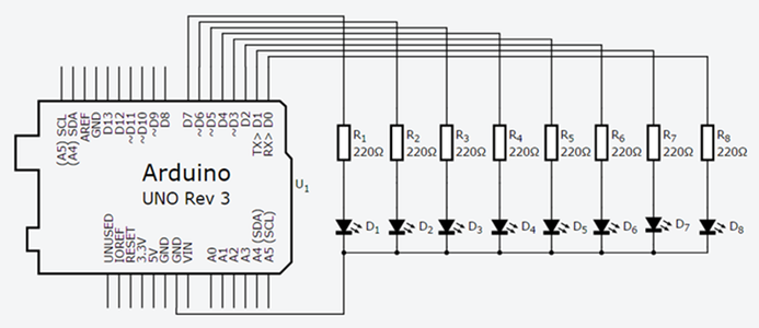
Try to be ordered with the distribution of cables. Use the properties of the components to adapt the characteristics thereof, such as wire color, resistance values, etc.
Step 16:

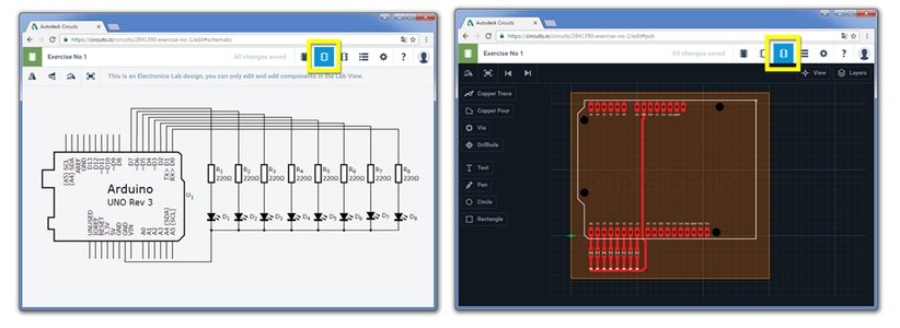
Autodesk Circuits is a very easy to use and very intuitive system. With practice you will notice that you can easily include components and make connections from one point to another very easily. As you go creating connections between components, you also can go simultaneously organizing a schematic diagram and a printed circuit for the subsequent manufacture of the PCB.
Step 17: BOM

Another important feature of this program is that you can find the Bill of materials (BOM) very easily, and is updated as the circuit, this list is also updated including new components and features:
Step 18: Handling I/O Ports
Exercise No. 1-0:
In some cases it is important to manage inputs and outputs as a group. In this way we can turn On or Off outputs individually or simultaneously, in a single line of program.
Arduino pins are assigned a port name:
· Port B (digital pin 8 to 13)
· Port C (analog input pins)
· Port D (digital pins 0 to 7)
If we wanted to work with pins 0 to 7, then we must refer to the "D" port, so we must then consider three directives for handling inputs or outputs:
DDRD - The Port D Data Direction Register - read/write
PORTD - The Port D Data Register - read/write
PIND - The Port D Input Pins Register - read only
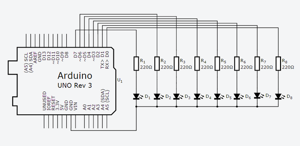
In this exercise we will work with pins 0 to 7. The first step will be to set all the pins as an output. Then we will see how turn On or Off some pins individually and simultaneously.
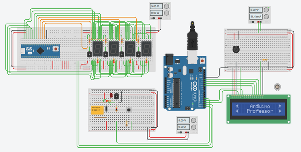
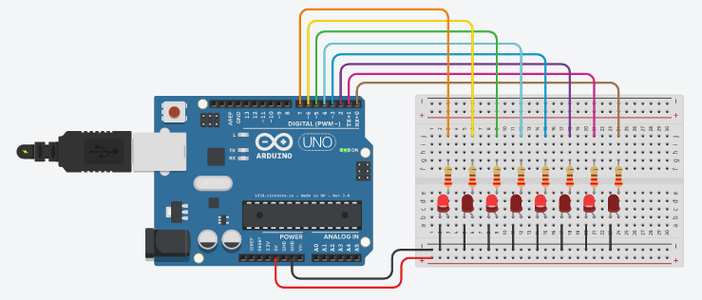
To perform this example, we will be based on the following circuit:
Step 19: Step 1.

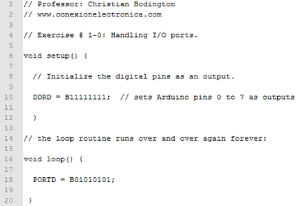
Set it up all pins as output or initialize the digital pin as an output.
· A number “1” means that the corresponding pin will be an output.
· A number “0” means that the corresponding pin will be an input.
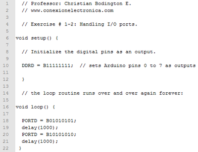
DDRD = B11111111; // sets Arduino pins 0 to 7 as outputs.
So, If we wanted to “turn On” the pins 0, 2, 4 and 6, we then run the following statement:
PORTD = B01010101;
(Exercise code No.1-0)
Step 20: Upload and Run, the Result Will Be.
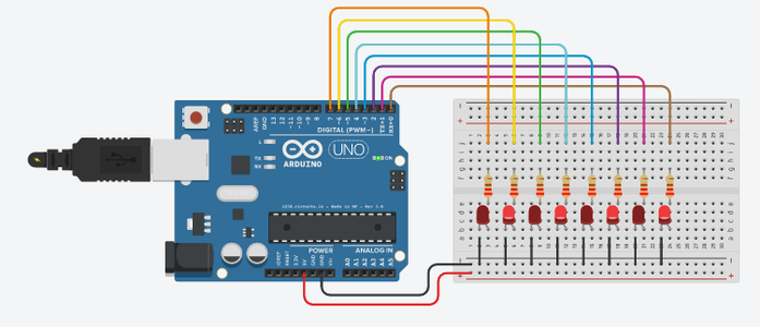
If we change the status of the outputs, ie, where we have put a number "1" put a "0", and vice versa:
PORTD = B10101010;
Attachments

Step 21: (Exercise Code No.1-1)

The result will be the following:
Attachments
Step 22:
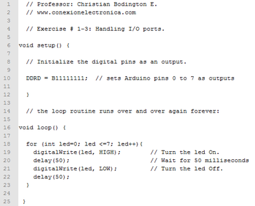
Now make a “loop” to toggle the LEDs:
(Exercise code No.1-2)
Step 23: Exercise No. 1-2:
Attachments
Step 24: Exercise No. 1-3:
Attachments
Step 25: Exercise No. 1-4
In this exercise we will include a potentiometer which will connect to one of the analog inputs of the circuit. The idea is to read the voltage level at the input A0, and convert this value into a digital number (binary), which should range between 0 and 255, and which may be displayed on the 8 LEDs connected to port D. Set the potentiometer value in 5 Kohms.
Step 26:
Video:
Attachments
Step 27: Viewing Data on an LCD Screen.
Exercise No. 2-0:
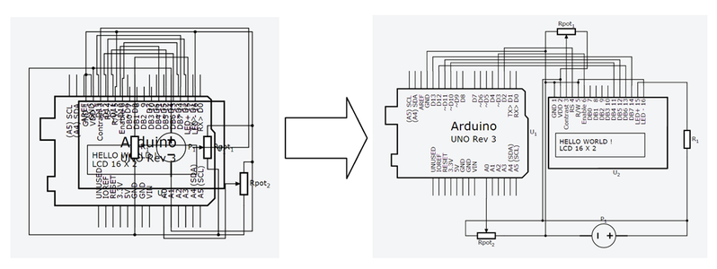
It would be more interesting to see the binary data of the previous exercise, in a decimal format displayed on an LCD screen. This implies that we reformulate the circuit in the previous example, installing an alphanumeric LCD display and manipulate a potentiometer connected to an input of the ADC converter.
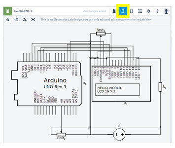
Step 28: We Could Present the New Design As Follows:

Step 29:
Once organized the circuit and made connections between components in Breadboard, proceed to organize the schematic diagram in the appropriate section:
Step 30: (Exercise Code No.2-0)
Step 31:
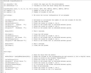
In this exercise we've done is read in the analog port A0 a voltage level ranging between 0 and 5 volts and this conversion store it in a variable named "sensorValue" which will be shown in the second row of the LCD .
Please read the comments in each line to a better understanding of programming logic.
Exercise No. 2-1:
Let us now try to include another potentiometer connected to the analog input A1 of the ADC converter, and simultaneously we show the results of both conversions on the LCD screen.
Attachments
Step 32:
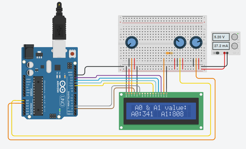
Step 33:
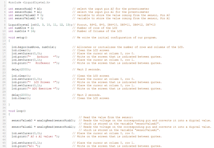

It is important to note that the values obtained in the A0 and A1 inputs vary between 0 and 1023, because the ADC converter Arduino UNO R3, consists of 16 bits.
Attachments
Step 34: Lets Add a Servo Motor to the Exercise No.4

A servomotor is an electromechanical device capable of rotating its axis at a specific position along its route, injecting a controlled pulse train to a control circuit which has within its box or chassis. This signal is applay through a control cable that distinguishes between the three wires owning and depending on the brand of the servomotor can be white or yellow. The power cables are distinguished by their black (negative) and red (positive).
A standard servomotor is well suited for robotics projects dimensions, and although can be found in different sizes, it is important to note that the strength of a servo on its axis is not directly proportional to size. This means that their strength depends to a great sense of interior design, ie, mechanical and materials that make up your gears.
Let's look at some important technical features in a standard servomotor:
- Control: PWM or Pulse Width Modulation
- Pulse: 3-5 Volt Peak to Peak.
- Operating voltage: 4.8 to 6.0 Volts.
- Torque (4.8V): 3.0 kg / cm (42 oz / in)
- Torque (6.0V): 4.5 kg / cm (48.60 oz / in)
- Operating Temperature Range: -20 to +60 ° C.
- Speed (4.8V): 0.19sec / 60 degrees.
- Speed (6.0V): 0.15sec / 60 degrees.
- Current (4.8V): 7.4mA and 160mA active in applying force.
- Current (6.0V): 7.7mA and 180mA when applying active force.
To control the axis position of a servomotor, you need to send a pulse train where the width of each pulse determines the point at which the axis maintains its position as long as it is present the pulse train. The travel of the axis will be in most models 180 degrees and timing for the pulse signal to the main positions (0 °, 90 ° and 180 °) are specified in the following table. (These times may vary according to the model and brand of servomotor).
Step 35:

So, if we want to position the axis in to 0°, should be introduced to the servo pulses of 0.6 milliseconds (T1) approximately every 20 milliseconds. T2 corresponds therefore while we wait to send a new pulse, which maintains current axis position. The time T2 may be within the range 10 ms ≤ T2 ≤ 40 ms.
Step 36:

As you gradually increase the time T1, the axis of the servomotor will go moving clockwise. When T1 = 1.5 ms can see that the axis forms an angle of 90° relative to the starting point (0°). You can be observed the signal corresponding to this position (90°), where T2 is maintained at 20 milliseconds.
Step 37:

The signal Corresponding to the maximum position (180°) in a standard servomotor, would then signal values for T1 and T2 = 2.6 ms = 20 ms.
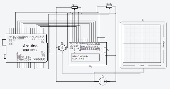
Step 38: Exercise 3-0. Servomotor + ADC + LCD

In the following example, we will move the axis of a servomotor in the range of 0 to 180 ° by turning the knob of a potentiometer connected to the input port "A0" (ADC Port).
Step 39:

Step 40: Download the Code
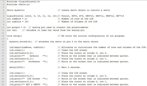

The first change is that we added the library "servo.h". Read the comments of the program. Note that we have included the "Map (value, fromLow, fromHigh, toLow, toHigh)" instruction. Analyze the function of this instruction, it is very easy to understand.
Step 41:
We can improve the performance if we include the value of the servo motor shaft position in the LCD:
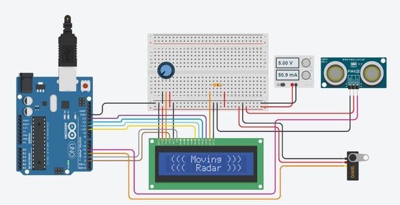
Step 42: Moving Radar
Now add an ultrasonic sensor to the previous exercise, and try to Understand as is the operation of this device. Let's see the theory on how to calculate the distance between the sensor and an object. The concept is to integrate a servomotor With This sensor, in order to make a radar to turn in a route of 180 degrees back and forth.
Step 43: Mount the Following Circuit (exercise 3-2):
Step 44:
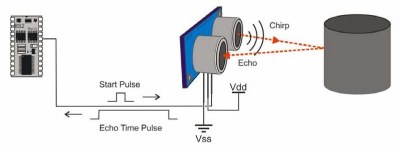
Before viewing the programming for this example, let's see how the ultrasonic sensor works and how the distance is calculated.
As you can see in the figure of Step 44, the sensor sends a brief chirp with its ultrasonic speaker, and the idea is to measure the time it takes the echo to return to its ultrasonic microphone. This time is call "the echo time pulse", and we can measure this time very easy with the "Pulsein" instruction.
Another important feature that we need to know about this sensor, is that is capable to give us a measure between 3 centimeters to 333 centimeters.
Pulsein returns the length of the pulse (in microseconds). We can save this value in a variable in order to calculate the distance from the object.
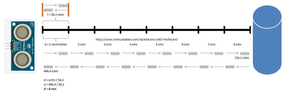
We also need to know that the sound velocity is V=343 m/s and we need this variable in centimeters, whitch is equal to V=34300 cm/s.
Then, we calculate the time for a distance of 1 centimeter:
t = 1 cm / (34300 cm/s)
t = 0,000029155 seconds. This is the time the signal takes to go to the object in 1 centimeter.
But the signal goes to the object and comes to the sensor, then this value must be multiplying by 2:
t = 0,000058309 seconds.
Now we make the conversion from seconds to microseconds:
t = 58,3 microseconds.
Here is an example of how to calculate the distance between the sensor and an object using this data:
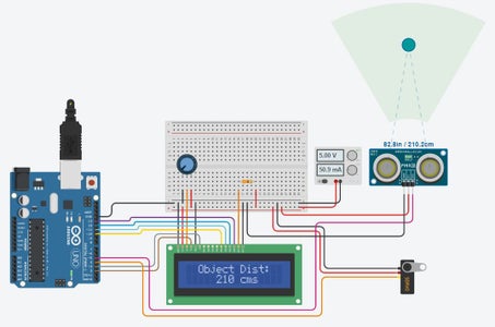
Step 45: Clic Over Next Image to See the Details
Analyze the program code (exercise 3-2), note that as the servo shaft rotates, the ultrasonic sensor scans the area to determine if there is an object in front, measuring the total distance.
Attachments
Step 46: Another Way to Program This Radar
Attachments
Step 47: 7 Segment Display.
Step 48: Let's Look at the Components Used and the Connections Made in This Exercise:
Then the code for the exercise 4-0 is included, read the comments on each program line, and try to simplify the code.
Attachments
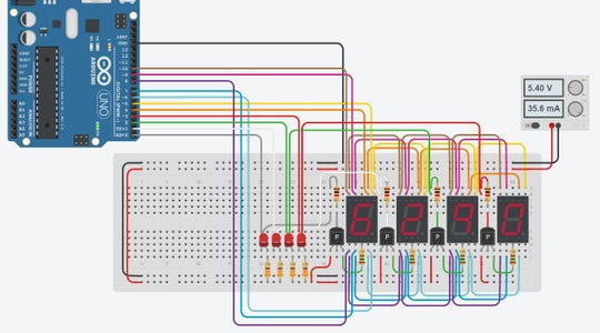
Step 49: 7-segment Display Multiplexing
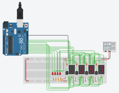
Step 50:
The idea of this exercise is to learn to use more than one 7-segment display, but with the least amount of I/O pins of the Arduino.
This time I decided connect four 7-segment display modules with common Anode configuration.
This means that for segments light up, the common anode of the display must be connected to + 5Vdc, and the cathode of each segment to GND.
But considering that we want to use the least amount of I/O pins as possible, what we do is connected in common segment A of each display, as well as the B of each display, the C of each display, and also to connect all common letters. Then we assign each letter a I/O pin on the Arduino UNO:
A segment --> PIN 4
B Segment --> PIN 5
C segment --> PIN 6
D Segment --> PIN 7
E segment --> PIN 8
F Segment --> PIN 9
G Segment --> PIN 10
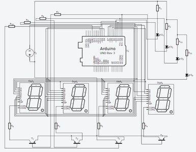
To activate the anode of each display, I used a generic PNP transistor (2N3906). This transistor connects the anode of the display to the Vcc power source only when we apply "0" (0 volts) at the base of the transistor. If you want the display to go, simply apply "1" (5 volts).
Then, as shown in the following circuit, connecting the anode of each display is performed as follows:
Attachments
Step 51: Video
Attachments
Step 52: Overcurrent:
Something interesting to note about Autodesk Circuits, is that the simulator is able to calculate the values of overcurrent which crosses the components, when the voltage in the power source exceeds the allowable limits for each case:
Step 53: H Bridge:
The following circuit is useful for controlling DC motors. We can control the motor rotation changing the status of the base in each transistor:
Now we add two push buttons with pull up resistor:
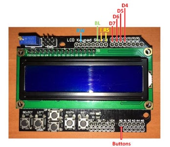
Step 54: LCD Keypad Shield

We will study below the LCD Shield, which in my opinion is one of the best ways to implement the use of an LCD display and a keypad for navigating menus.
For less than $ 5 you can purchase this Shield (www.Aliexpress.com), in order to build and program a lot of applications or exercises.
The interesting thing about this module is that it has 5 buttons connected in a very particular way. All can be read with only one Pin of the Port "C". In this case, each switch generates a voltage between 0 and 5 volts at Pin A0 on the ADC.
Specifically this:
- When all buttons are idle, the voltage at A0 is equal to 5Vdc.
- When you press the "Right" button, A0 = 0 Vdc.
- When you press the "Up" button, A0 = 0.64 Vdc.
- When you press the "Down" button, A0 = 1.5 Vdc.
- When you press the "Left" button, A0 = 2.35 Vdc.
- When you press the "Select" button, A0 = 3.53 Vdc.
These values are calculated from the conversion performed by the ADC, so the conversion results are:
- When all buttons are idle, the value read on A0 is "1023".
- When you press the "Right" button, the value read on A0 is "0".
- When you press the "Up" button, the value read on A0 is "131".
- When you press the "Down" button, the value read on A0 is "308".
- When you press the "Left" button, the value read on A0 is "481".
- When you press the "Select" button, the value read on A0 is "722".
Now let's do the math to check:
Remember that the ADC converter is 16 bits, then the read range of value ranges is 0-1023.
- If the result of the conversion is equal to: 1023
5 Volts ---------------------> 1023
X --------------> Conversion: 1023
X = (1023 x 5V) / 1023
X = 5 Volts.
- If the result of the conversion is equal to: 0
5 Volts ---------------------> 1023
X --------------> Conversion: 0
X = (0 x 5V) / 1023
X = 0 Volts.
- If the result of the conversion is equal to: 131
5 Volts ---------------------> 1023
X --------------> Conversion: 131
X = (131 x 5V) / 1023
X = 0.64 Volts.
- If the result of the conversion is equal to: 308
5 Volts ---------------------> 1023
X --------------> Conversion: 308
X = (308 x 5V) / 1023
X = 1.5 Volts.
- If the result of the conversion is equal to: 481
5 Volts ---------------------> 1023
X --------------> Conversion: 481
X = (481 x 5V) / 1023
X = 2.35 Volts.
- If the result of the conversion is equal to: 723
5 Volts ---------------------> 1023
X --------------> Conversion: 723
X = (723 x 5V) / 1023
X = 3.53 Volts.
Step 55: Let's Do a Program to Read the Conversion Value of Each Button in A0, and Show the Value on the Screen:
Attachments
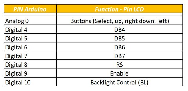
Step 56: Pinout
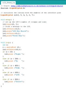
Step 57: Code


Step 58: Now Try With This Code:
Attachments
Step 59: Arduino and SIM900 - Exercise

Then we learn to control a SIM900 module via SMS, in order to take control of four relays, to turn on and off independently or all at once.
To make this practice have used the following components:
- Arduino UNO.
- SIM900 Shield: http://www.geeetech.com/gprsgsm-sim900-shield-boar...
- ProtoShield prototype expansion board with mini bread board based FOR ARDUINO: https://www.aliexpress.com/item/ProtoShield-protot...
- 4 Four Channel Relay Module DC 5V + Optocoupler For Arduino PIC ARM AVR DSP: http://www.ebay.com/itm/4-Four-Channel-Relay-Modul...
Check the SIM900 module does not require much effort. For a better understanding, please check the following link:
The first thing to know is that this module can be controlled via AT commands. There is a long list of available commands, however, to send and receive SMS text messages, simply use a small amount of AT commands.
In the video above you can see how we have managed to turn on and off relays via an SMS text message. But to get to that point we will verify how this module connected with the Arduino UNO, we will send AT commands from the Arduino, and we will observe from the serial monitor the response of SIM900.
Communication between the arduino UNO and the SIM900 module is done through serial communication, but there are two ways to communicate with the SIM900 module:
- Via Software Serial Selected.
- Via Hardware Serial Selected.
You must select one of two options in the following Jumper:
Step 60:

We will start this practice selecting: "Software Selected Serial"
Another important thing you should consider having, is a SIMCARD with a plan of SMS text messages.
The assembly of these parts with Arduino ONE would follows:
Use the following procedure to send an SMS text message to your cell phone:
Step 61: Relays Control Program Via SMS:

Step 62:

Participated in the
Circuits Contest 2016


