

Introduction: ☠WEEDINATOR☠ Part 2: Satellite Navigation


The Weedinator navigation system is born!
A roving agricultural robot that can be controlled by a smart phone.
... And rather than just go through the regular process of how it's put together I thought I'd try and explain how it actually works - obviously not EVERYTHING but the most important and interesting bits. Please excuse the pun, but it's how the data flows between the individual modules that I find interesting and broken down into it's lowest denominator we end up with actual "bits" - zeros and ones. If you're ever been confused about bits, bytes, characters and strings then now may be the time to become unconfused? I'm also going to try and unconfuse a slightly abstract concept called 'Error Cancelling'.
The system itself features:
- GPS/GNSS: Ublox C94 M8M (Rover and Base)
- 9DOF Razor IMU MO digital compass
- Fona 800H 2G GPRS cellular
- 2.2" TFT screen
- Arduino Due 'Master'
- Various Arduino 'Slaves'.
Strangely, a lot of Sat Navs don't have a digital compass which means if you are stationary, and lost, you have to walk or drive in any random direction before the device can show you the correct direction from satellites. If you get lost in a thick jungle or underground car park you're stuffed!
Step 1: How It Works

At present, a simple pair of coordinates is uploaded from a smart phone or computer, which are then downloaded by the Weedinator. These are then interpreted into a heading in degrees and a distance to travel in mm.
The GPRS fona is used to access an online database through the 2G cellular network and receive and transmit the coordinates to the Arduino Due via an Arduino Nano. The Due is the Master and controls an array of other Arduinos as Slaves via the I2C and serial buses. The Due can interact with live data from the Ublox and Razor and display a heading calculated by one of it's Arduino slaves.
The Ublox satellite tracker is particularly clever as it uses error cancelling to get very accurate fixes - a final nominal total deviation of about 40mm. The module is composed of an identical pair, one of which, the 'rover', moves with the Weedinator, and the other, the 'base' is fixed onto a pole somewhere out in the open. Error cancellation is achieved by the base being able to achieve a really accurate fix by using a large amount of samples over time. These samples are then averaged to compensate for changing atmospheric conditions. If the device was moving, it obviously would not be able to get any kind of averaging and would be at the complete mercy of a changing environment. However, if a static and moving device work together, as long as they can communicate between one another, they can get the benefit of both. At any given time, the base unit still has an error but it also has a previously calculated super accurate fix so it can calculate the actual error by subtracting one set of coordinates from another. It then sends the calculated error to the rover via a radio link, which then adds the error onto it's own coordinates and hey presto, we have error cancelling! In practical terms, error cancellation makes the difference between 3 metres and 40mm total deviation.
The complete system looks complicated, but is actually fairly easy to build, either loose on a non conductive surface or using the PCB that I designed, which allows all modules to be securely bolted on. Future development is built onto the PCB, allowing a vast array of Arduinos to be incorporated to control motors for steering, forward motion and an on-board CNC machine. Navigation will also be assisted by at least one object recognition system using cameras to sense coloured objects, for example fluorescent golf balls, which are carefully positioned in some kind of grid - Watch this space!
Step 2: Components


- Ublox C94 M8M (Rover and Base) x 2 of
- 9DOF Razor IMU MO digital compass
- Fona 800H 2G GPRS cellular 1946
- Arduino Due
- Arduino Nano x 2 of
- SparkFun Pro Micro
- Adafruit 2.2" TFT IL1940C 1480
- PCB (see attached Gerber files) x 2 of
- 1206 SMD zero ohm resistors x 12 of
- 1206 LEDs x 24 of
The PCB file opens with 'Design Spark' software.
Attachments

Step 3: Wiring Up the Modules

This is the easy part - especially easy with the PCB that I got made - just follow the diagram above. Care is needed to avoid wiring 3v modules to 5v, even on the serial and I2C lines.
Step 4: Code

Most of the code is concerned with getting data to move around the system in an orderly manner and quite often there is a need to convert data formats from integers to floats to strings and to characters, which can be very confusing! The 'Serial' protocol will only handle characters and whilst the I2C protocol will handle very small integers, I found it better to convert them to characters and then convert back to integers at the other end of the transmission line.
The Weedinator controller is basically a 8 bit system with lots of individual Arduinos, or 'MCU's. When 8 bit is described as actual binary zeros and ones it can look like this: B01100101 which would equal:
(1x2)+(0x2)2+(1x2)3+(0x2)4+(0x2)5+(1x2)6+(1x2)7+(0x2)8 =
| Decimal Digit Value | 128 | 64 | 32 | 16 | 8 | 4 | 2 | 1 | |
| Binary Digit Value | 0 | 1 | 1 | 0 | 0 | 1 | 0 | 1 |
= 101
And the maximum value possible is 255 .... So the maximum integer 'byte' we can transmit over I2C is 255, which is very limiting!
On an Arduino we can transmit up to 32 ASCII characters, or bytes, at a time using I2C, which is much more useful, and the character set includes numbers, letters and control characters in 7 bit format as below:
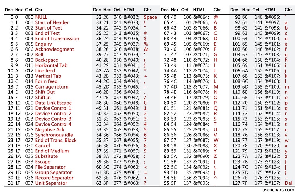
Fortunately, the Arduino compiler does all the work of conversion from character to binary in the background, but it still expects the correct type of character for data transmission and it won't accept 'Strings'.
Now is when things can get confusing. Characters can be expressed as single characters using the char definition or as a one dimensional array of 20 characters using char[20]. An Arduino String is very similar to a character array and is literally a string of characters often interpreted by the human brain as 'words'.
// Builds the character 'distanceCharacter':
      String initiator = "";
      distanceString =  initiator + distanceString ;
      int n = distanceString.length();
      for (int aa=0;aa<=n;aa++)
      {
          distanceCharacter[aa] = distanceString[aa];
      }
The code above can convert a long string of characters into a character array of characters which can then be transmitted over I2C or serial.
At the other end of the transmission line, the data can be converted back to a string using the following code:
distanceString = distanceString + c; // string = string + character
A character array can not be converted directly to an integer and has to go into the string format first, but the following code will convert from a string to an integer:
      int result = (distanceString).toInt();
      int distanceMetres = result;
Now we have an integer which we can use to make calculations. Floats (numbers with a decimal point) need to be converted to integers at the transmission stage and then divided by 100 for two decimal places eg:
float distanceMetres = distanceMm / 1000;
Lastly, a string can be created from a mixture of characters and integers eg:
// This is where the data is compiled into a character:

 dataString = initiator + "BEAR" + zbearing + "DIST" + zdistance;  // Limited to 32 characters

//  String  =  string + characters + intereger + characters + integer.
The rest of the code is standard Arduino stuff that can be found in the various examples in the Arduino libraries. Check out the 'examples >>>> Strings' example and the 'wire' library examples.
Here's the whole process for transmit and receive a float:
Convert Float ➜ Integer ➜ String ➜ Character[ ] array ..... then TRANSMIT character array from Master ➜➜
➜➜ RECIEVE individual characters on Slave .... then convert Character ➜ String ➜ Integer ➜ Float
Step 5: Database and Webpage


Above is shown the database structure and the php and html code files are attached. Usernames, database names, table names and passwords are blanked out for security.
Attachments
Step 6: Navigation Tests


I managed to hook up a datalogger to the Weedinator control board via I2C and get some idea of the Ublox M8M satellite positioning performance:
On 'Cold Start', shown by the green graph, the module started off with lots of error, quite similar to a 'normal' GPS, and gradually the error became reduced until, after about 2 hours, it got a RTK fix between rover and base (shown as the red cross). During that 2 hour period, the base module is continually building up and updating an average value for latitude and longitude and after the pre-programmed time interval decides that it has got a good fix.The next 2 graphs shows behaviour after a 'Hot start' where the base module has already calculated a good average. The top graph is over a 200 minute period and occasionally the fix is lost and the rover sends a NMEA message to the Weedinator that the fix has temporarily become unreliable.
The lower blue graph is a 'zoom in' on the red box in the top graph and shows a good representative snap shot of the Ublox performance, with total deviation of 40 mm, which is more than good enough to guide the Weedinator to it's loacation, but possibly not good enough to cultivate the soil around individual plants?
The third graph shows data gathered with the Rover and Base 100 metres apart - No additional error was detected - the distance of separation made no difference to the accuracy.
Step 7: Final


I'm very happy with how the Weedinator control system is turning out :) The data seems to flow between the different modules without any particular problem and the foundations for additional modules seems to be pretty solid with plenty of room for motor controllers and object recognition systems.
In the meantime, the Weedinator chassis design has progressed to the stage where it has an on board CNC machine for cultivating the soil. It will soon be time to get back to the workshop to do some more fabrication.
*Special thanks to SlashDevin for the Ublox NMEA Arduino code.
☠

Participated in the
Remote Control Contest 2017

Participated in the
Arduino Contest 2017


