

Introduction: Arduino Controlled Smart Hydroponic Modular System


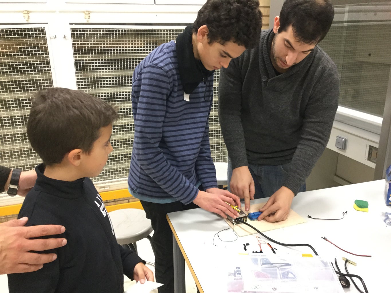
We love electronic and plants, so we created a hydroponic system during the activity "Robotics in family" in the Juan de Lanuza School.
We wanted to create a portable system in order to show it to all the school and to cultivate regional plants during the year.
Hydroponics
Hydroponics for us is not only an enjoyable hobby, it is also a green one.
Hydroponics uses as little as 10% of the water needed for plants grown in dirt, and results in higher yields due to the plants always having the necessary nutrients available to them when they need it.
Being a closed system it also means that fertiliser is kept out of the water table, which is great for the environment.
Step 1: Project
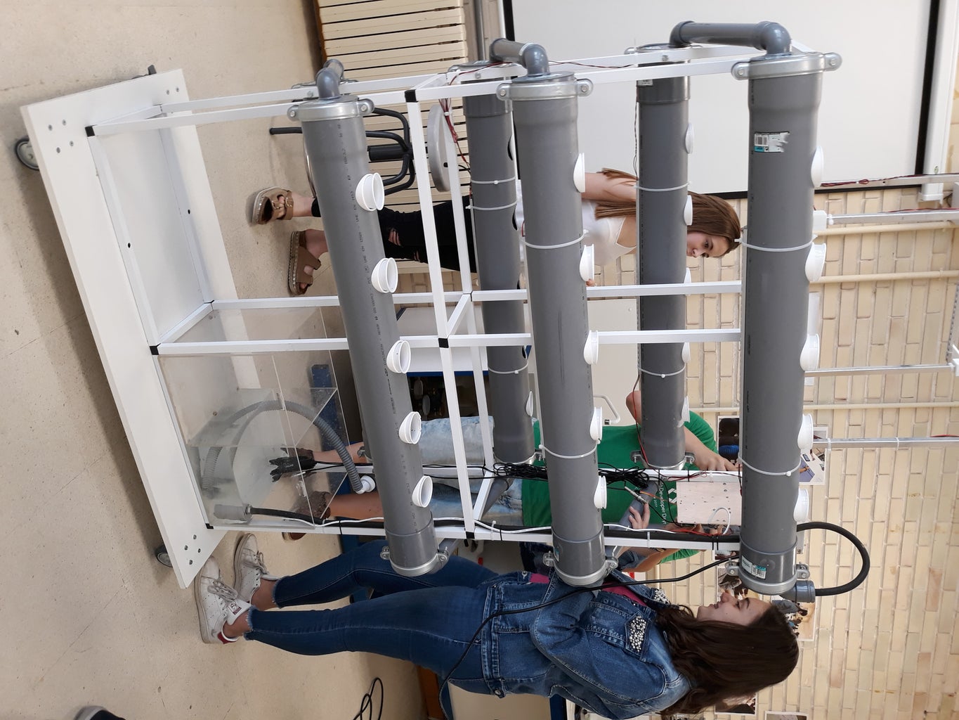
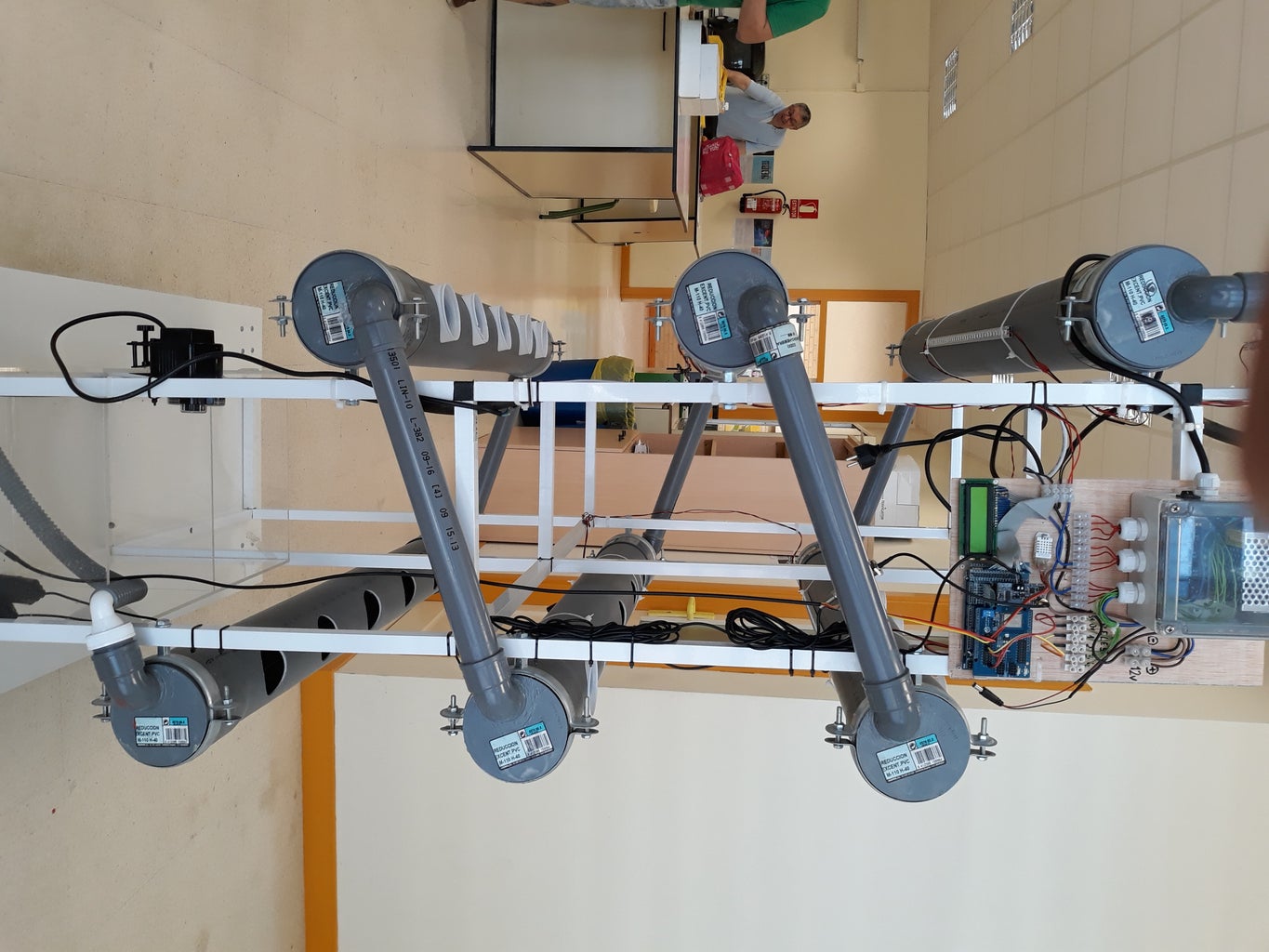
Our project is a hydroponic cultivation, an indoor cultivation based on hydroponics, a method used to grow plants using mineral solutions instead of soil. The general structure is made of aluminum. The structure through which the water circulates consists of PVC pipes cut and glued by hand, and consists of 6 levels through which the water passes. Each level has been drilled to place pots. 3D pieces have also been designed so that the pots do not move and to support the lighting. In the lower part there is a tank in which the water of the system falls and through which different components can be added to the water. In case of having to drain the tank, we have a manual drain.
Our platform consists of three different parts:
Modular structure: PVC and aluminium frame in order to support all the hydroponic system.
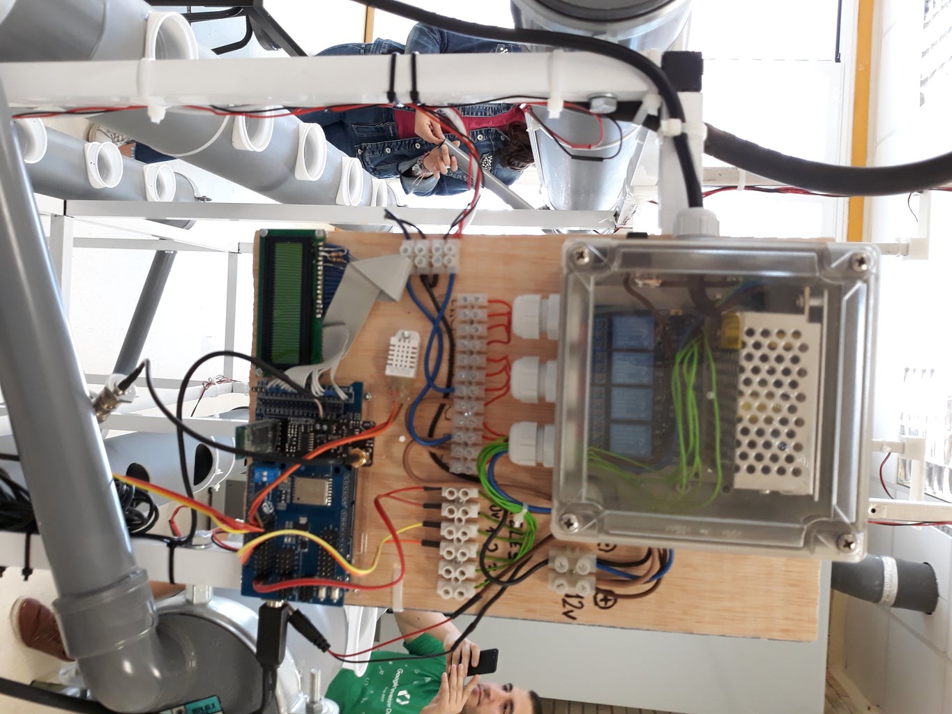
Electronic circuit: main control of the digital "brain" of our system
Sensors/actuators: measure and control all the data and parameters of our system.
The device allows to control the state of the plants by sensing several parameters:
- Air temperature and humidity
- Water temperature
- pH
- Conductivity
- Time
Then it uses different types of actuators to modify the state of the plants by irrigating them, activating lights or releasing nutrients:
- Water pump
- Growing light
- Nutrient feeder
The device periodically sends the information to a web server using WiFi. We have also designed an App that allows this data to be visualized from an Android device. We have released it as open source code.
Step 2: Materials


Structure materials:
- 100mm Diameter PVC tube x6 meters
- 40mm Diameter PVC tube x2 meters
- 100-40mm PVC connector x12
- 40-10mm PVC connector x1
- 90º 40mm connector x12
- Water acrylic deposit (or 5l bottle)
- Flexible 10mm tube x 2 meters
- 2m wood table 2x1x1 meters
- Aluminium frame x 16 meters
- Aluminium 3 frames connector x8
- Aluminium 4 frames connector x8
- Aluminium 5 frames connector x2
- Wheel x4
- PVC glue
Electronic/electric materials:
- Arduino MEGA: https://es.aliexpress.com/store/product/Env-o-Lib...
- Arduino MEGA box: https://es.aliexpress.com/store/product/Enclosure...
- Protoboard MEGA: https://es.aliexpress.com/store/product/1set-for-...
- Connector protoboard MEGA: https://es.aliexpress.com/store/product/Free-ship...
- 12v power supply: https://es.aliexpress.com/store/product/AC-DC-12V...
- Relay module: https://es.aliexpress.com/store/product/With-opto...
- ESP8266 module: https://es.aliexpress.com/store/product/ESP8266-E...
- HC05 module: https://es.aliexpress.com/store/product/Origial-W...
- Temperature sensor waterproof: https://es.aliexpress.com/store/product/Origial-W...
- Temperature and humidity ambient sensor: https://es.aliexpress.com/store/product/AM2302-DH...
- Water pump: https://es.aliexpress.com/store/product/DC12V-1-9...
- PH/conductivity board: https://www.cooking-hacks.com/hydroponics-aquapon...
- PH sensor: https://www.cooking-hacks.com/ph-sensor
- Conductivity sensor: https://www.cooking-hacks.com/conductivity-sensor
- Grow light: https://es.aliexpress.com/store/product/10pcs-0-5...
- Fish feeder: https://es.aliexpress.com/store/product/Bater-a-O...
Others:
- Plant pots
Tools:
- Rotary Hand Tool
- Hand Drill
- Soldering Iron
- Wire stripper
- Hot glue Gun
- Hole Saw
- Clamps
- Saw
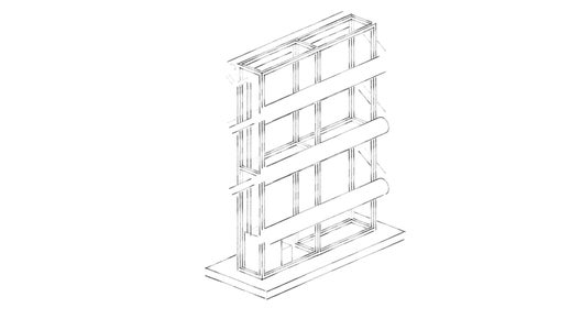
Step 3: Modular Frame


A modular low cost hydroponic system was designed for this project.
Connect the PVC pipes using different size connectors as shown in the main diagram.
Construction Steps
- Cutting lengths of PVC
- Fitting everything together
- Drilling
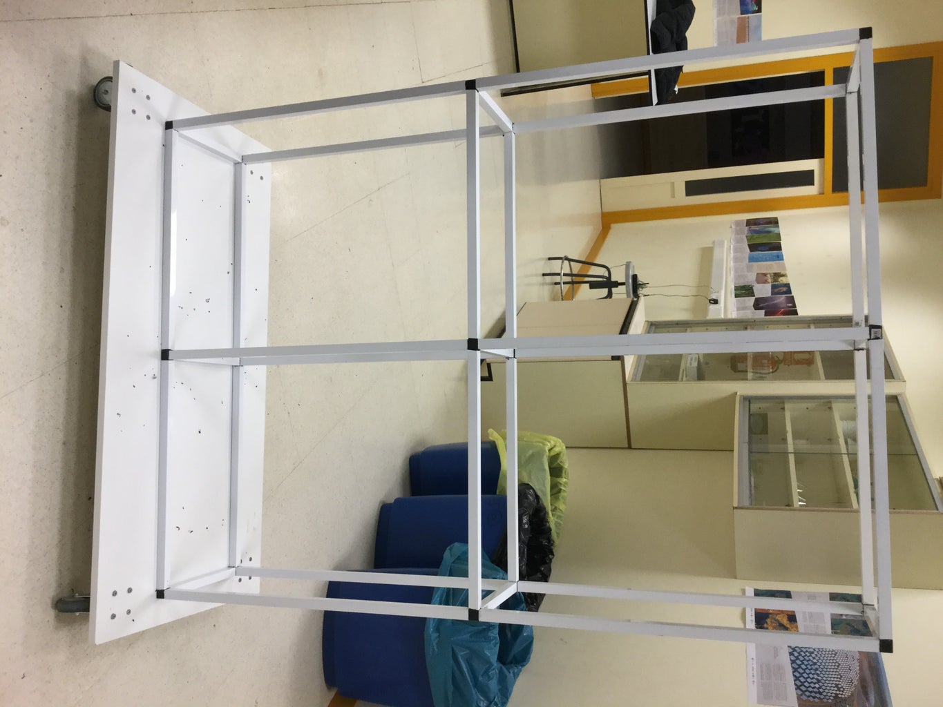
Support Frame
We need a frame to support our pipes. The frame was constructed from aluminium for its modular properties (ease to fit several modules together) and the ease of use for sizing (easy to cut straight with basic tools).
Modular Base
We integrated a modular wood base with 4 wheels in order to create a portable system.
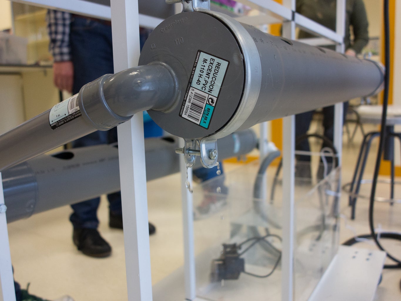
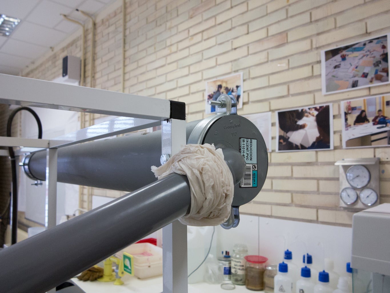
Step 4: PVC Assembly
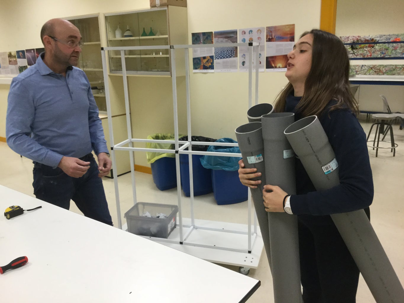


We glued our individual leg components together to increase stability.
The dimensions of the structure dictate the size of the hydroponic system and the number of rows the system can support.
Our current model includes 6 levels. The spacing can be modified to support more growing areas by decreasing spacing between the rows.
Note: PVC pipes for this project are best cut using a mitre saw. These are readily available in two types: inexpensive manual saws or time-efficient electric saws.
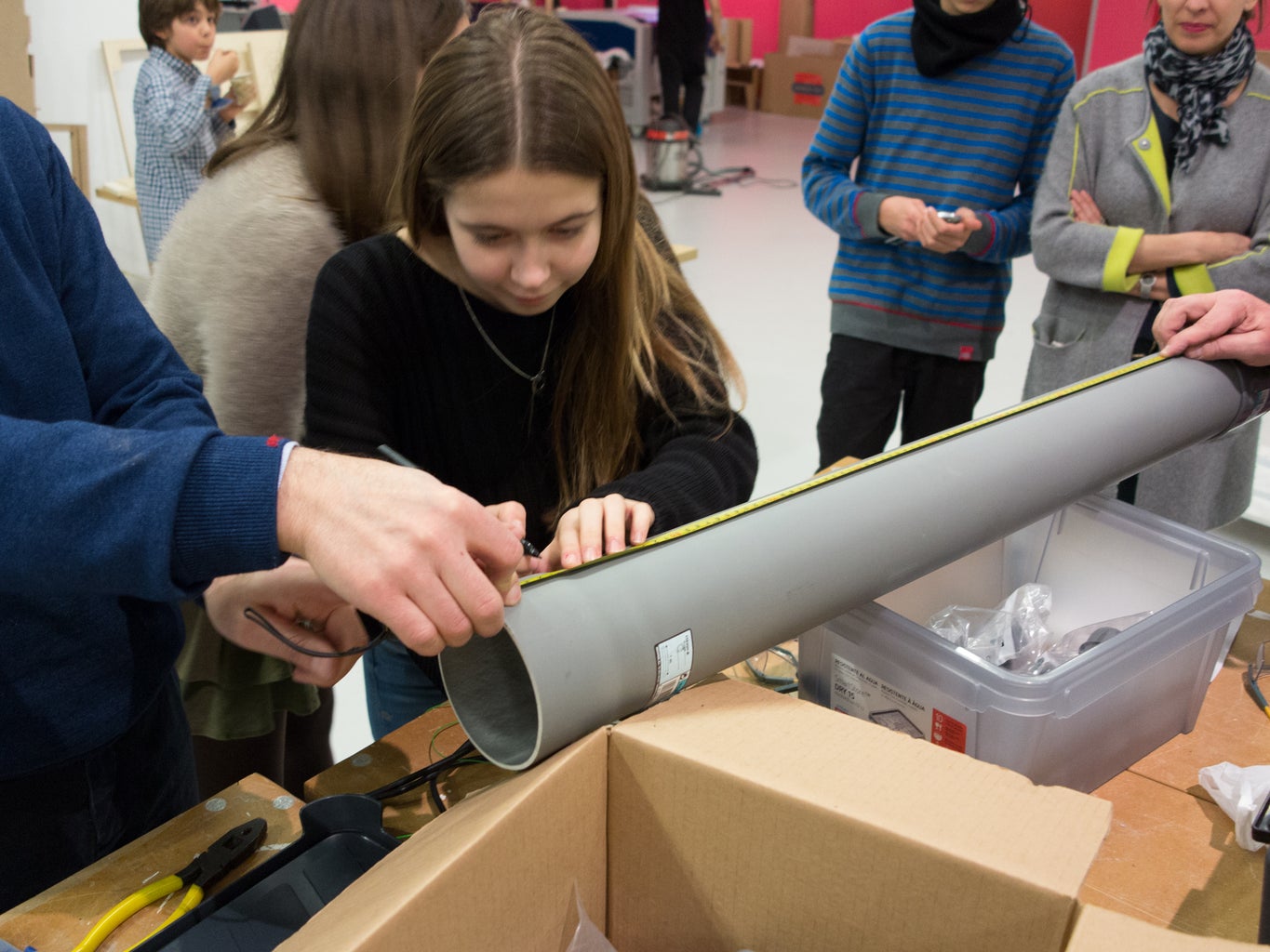
Step 5: Plant Holes


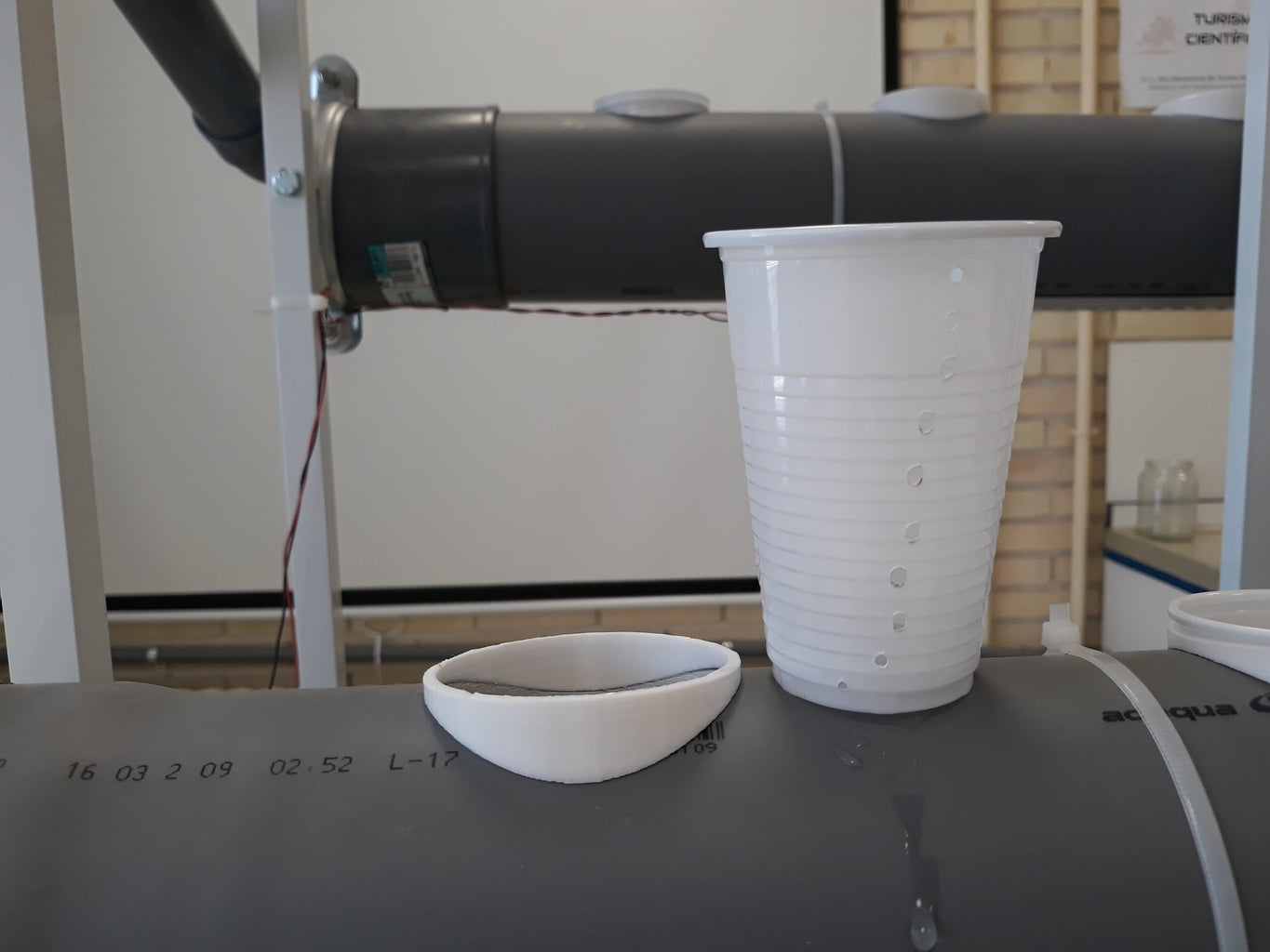
We drilled 5 to 7 holes in each tube. First, mark the point of each hole. Get your dremel tool with a grinding head and clean up the hole until the cups fit as you intended.
We used plastic glasses as plant plots. If you use them too, drill holes in the bottom and edges so that the roots can touch the water outside of the glass.
Use the cups to measure out clay balls into a bucket of water. The water will wash off any dust that might be in the balls.
Step 6: Hydroponic Structure


In hydroponics, it is all about getting the nutrient rich water to the plant's roots while making sure there is still enough oxygen in the water.
We created an NFT (nutrient film technique) system. For this, we needed a small, but constant flow of water that the plant's roots can enter in contact with.
The water contains all the nutrients the plants want, while the constant flow makes sure there is plenty of oxygen in the water.
The plants need something to support them and, although we won't have soil to hold them up, this is where hydroponic mediums come in. We used the expanded clay balls above mentioned. These give the plants support, and a small buffer to hold water.
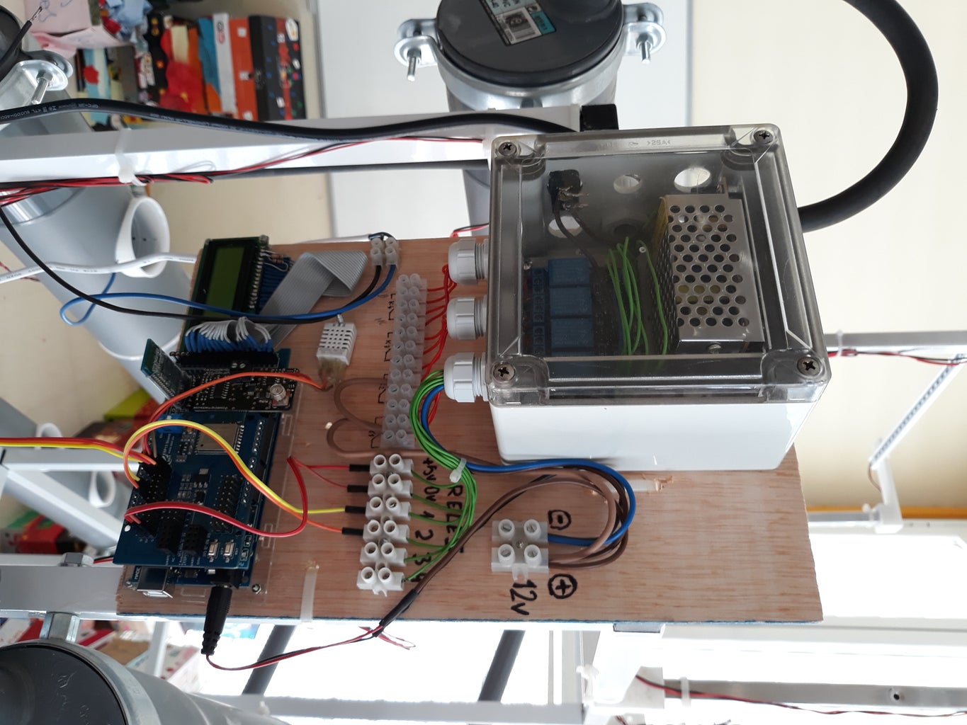
Step 7: Electrical Connection
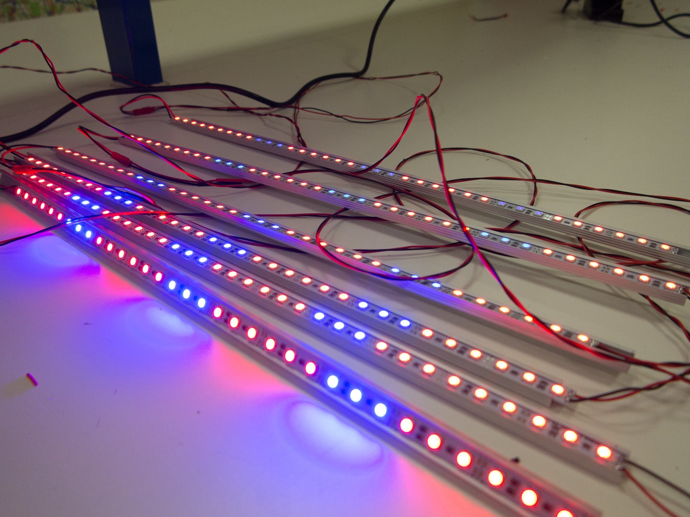


We connect all the cables and electric system using aluminium frame as support. It is connected to 220V using a 3A 12V power supply.
On top of the structure we connected growing lights. Ours are 12V LED strips and consume approximately 0.5A per metre of length. At the bottom we connected the water pump that uses 1A.
The main circuit consumption is of around 0.5A.
Step 8: 3D Printed Supports

We designed different 3D printed parts in order to support the different elements:
- Plant pots / plastic glasses: we created round supports to fit them on top of the pipes.
- Growing lights: we created supports to place them on the aluminium frame.
We used Tinkercad, a very simple online 3D CAD program, which you can use here: www.tinkercad.com


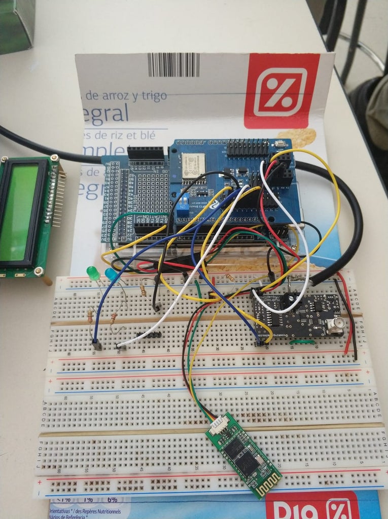
Step 9: Electronic Circuit

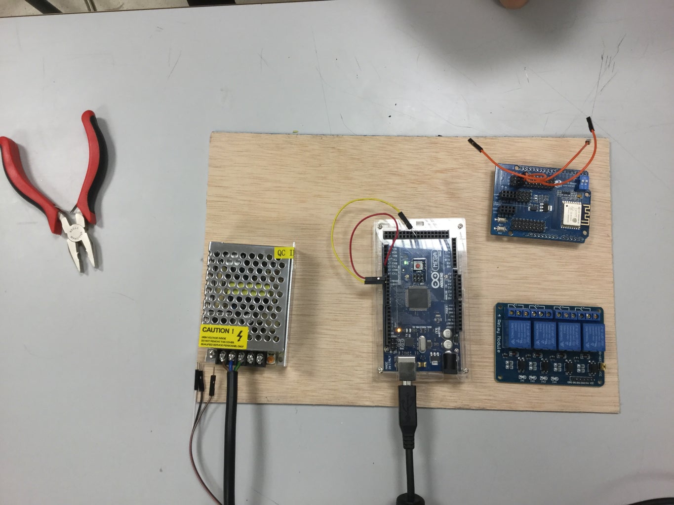

Here you can find the main diagram of the hydroponic circuit and the pinout of the project.
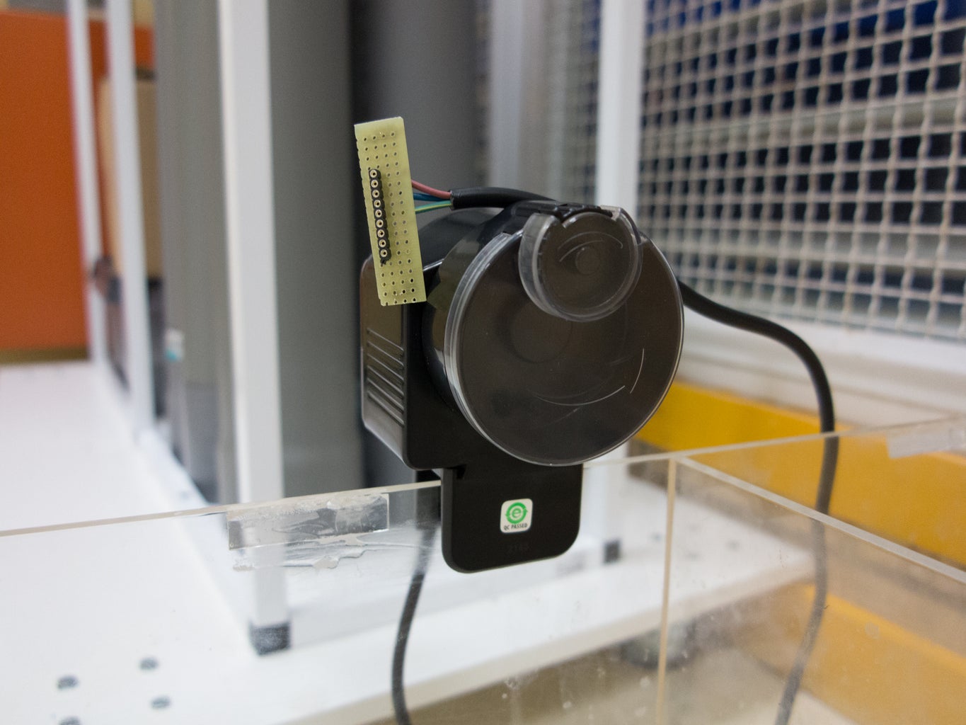
Step 10: Water Pump


We used a waterproof pump to lift the water from the tank in the floor to the top of the structure.
Step 11: Nutrients Feeder

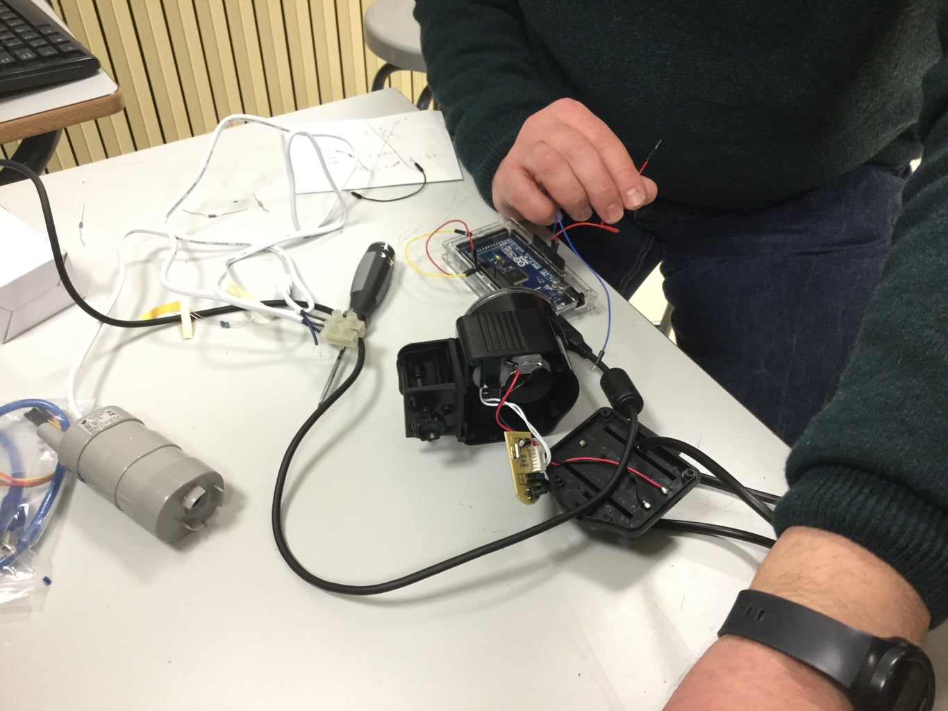

Hydroponic cultivations need special nutrients, as normal fertilisers are formulated to be used with soil and should not be used in hydroponics.
Fertilisers for hydroponics can come in different types depending on the different stages of plant growth and the type of crop.
We hacked a "fish feeder" in order to control it with an Arduino. It is our personalized nutrient feeder. We control it when we want so that we can release more nutrients to the water tank. Then we turn the water pump back on so that the plants receive nutrients.
Step 12: Hydroponic Sensors


The nutrients have to be added periodically, and it is hard to tell when it needs to be done. People do it anywhere from once a week to once a month, and it depends on how much fertiliser you add each time.
Another option is to control the pH and conductivity levels to adjust the fertiliser quantities accordingly.
We have integrated 2 specific sensors for hydroponic systems.
PH sensor
The pH sensor probe has a BNC connector which integrates all the different wires of the sensor.
Features:
- Measure range: 0~14pH
- Applicable temperature: 0~60°
- CBNC connector
- Cable: 2.9 meter
- Analogic output
Calibrating the sensor
In order to calibrate the pH sensor a pH calibration kit is needed.
Conductivity sensor
The electric conductivity sensor probe has two contacts which are not polarised and therefore are interchangeable.
Features:
- Applicable temperature: 0~60°
- CBNC connector
- Cable: 2.9 meter
- Analogic output
Calibrating the sensor
In order to calibrate the EC sensor you need a conductivity calibration kit
Step 13: Main Code


The goal was to implement automation using Arduino MEGA. This included:
- Water cycles by timers
- Light by timers
- Data measurement
- Nutrition by measurement (electric conductivity) and corrective action via nutrient dosing
- Pump control
- Water quality (pH) by measurement
- IoT Integration
- Data collection
- Recording of sensor measurements and actions
We have attached the main Arduino code for the project. If you are using a different pH or conductivity sensor, the calculations may need to be changed in order to obtain real values.
Arduino procedure
Keeps the time
Reads sensors
Communicates with the App via Bluetooth:
- Sends data (pH, conductivity, water temperature, air temperature, air humidity, arduino time, pump status and light status)
- Receives the update of the time from the AppTurns the pump on / off for certain minutes every hour
Turn the lights on / off
Transmits data to ThingSpeak at 15 minute intervals (pH, conductivity, water temperature, air temperature, air humidity)
Libraries:
We have included all the libraries used.
Code:
// HidroponicoCole_v5.8 NO CLAVES//
// bluetooht RX3-TX3
// DALLAS pin 3
// DHT pin 2
// Bomba pin 6
// Luz pin 7
// Shield ESP 8266 con comandos AT
// Utiliza libreria TimeLib para la fecha y hora
// Envia datos cada 15 minutos
// LCD con ALARMAS
// Invierte salida Bomba y Luz 0= activo, 1= inactivo
// -----------------------------------------------------------</p><p>#define DEBUG 0                                // change value to 1 to enable debuging using serial monitor
String network = "SSID NAME";                  // your access point SSID
String password = "PASSWORD";                  // your wifi Access Point password
#define IP "184.106.153.149"                   // IP address of thingspeak.com  184.106.153.149
String GET = "GET /update?key=CHANNEL_KEY";    // replace with your channel key</p><p>#include "OpenGarden.h"
#include
#include
#include
#include

#include </p><p>// initialize the library by associating any needed LCD interface pin
// with the arduino pin number it is connected to
const int rs = 51, en = 53, d4 = 39, d5 = 37, d6 = 35, d7 = 33;
LiquidCrystal lcd(rs, en, d4, d5, d6, d7);</p><p>// Establece valores inicio de fecha y hora
int hora = 9;
int minuto = 0;
int segundo = 0;
int dia = 1;
int mes = 1;
int ano = 17;</p><p>bool nuevoSegundo;
int viejoSegundo = 0;</p><p>bool nuevoMinuto;
int viejoMinuto = 0;</p><p>bool nuevaHora;
int viejaHora = 0;</p><p>// variables telegrama recibido de bluethooh
// cabecera, cuerpo1, cuerpo2, cuerpo3, fin
int cabecera = 0;
int cuerpo1 = 0;
int cuerpo2 = 0;
int cuerpo3 = 0;
int fin = 0;</p><p>// Sensores PH y EC
#define calibration_point_4 2246  //Write here your measured value in mV of pH 4
#define calibration_point_7 2080  //Write here your measured value in mV of pH 7
#define calibration_point_10 1894 //Write here your measured value in mV of pH 10</p><p>#define point_1_cond 40000   // Write here your EC calibration value of the solution 1 in µS/cm
#define point_1_cal 40       // Write here your EC value measured in resistance with solution 1
#define point_2_cond 10500   // Write here your EC calibration value of the solution 2 in µS/cm
#define point_2_cal 120      // Write here your EC value measured in resistance with solution 2</p><p>/*   SENSOR DHT22 (AIRE)  */
#define DHTPIN 2
#define DHTTYPE DHT22</p><p>float TemperaturaAire;
float HumedadAire;
DHT dht(DHTPIN, DHTTYPE);</p><p>/*   SENSOR Temperatura DALLAS  (TemperaturaAgua) */
#define ONE_WIRE_BUS 3
OneWire oneWireBus (ONE_WIRE_BUS);
DallasTemperature sensors (&oneWireBus);
float TemperaturaAgua;</p><p>/*   BOMBA y LUZ   */
#define PinBombaAgua 6  // Bomba en pin 6
#define PinLuz 7        // Luces en pin 7
#define Amanece 8      // Hora de encendido Luz
#define Anochece 20    // Hora apagado Luz
#define MinutosBomba 20    // Minutos funcionando bomba
bool BombaAgua = 0;   // 0=parada , 1= marcha
bool Luz = 0;         // 0= apagada , 1= encendida</p><p>// VALORES DE ALARMAS
#define PhAlto 10          // Valor alto alarma Ph
#define PhBajo 5           // Valor bajo alarma Ph
#define EcAlto 3000        // Valor alto alarma Ec
#define EcBajo 900         // Valor bajo alarma Ec
// Valor EcMuyBajo activa "Falta de agua". NO PERMITE FUNCIONAMIENTO BOMBA
#define EcMuyBajo 200
#define TempAguaAlto 40    // Valor alto alama Temp Agua
#define TempAguaBajo 5     // Valor bajo alama Temp Agua
int AlarmaPH;         // alarma Ph
int AlarmaTempAgua;   // alarma Temp
int AlarmaEC;         // alarma Ec</p><p>float pH;
float EC;</p><p>void setup() {
  lcd.begin(16, 2);                 // Inicia LCD 16 caracteres, 2 filas
  // Mensaje de arranque en LCD
  borrarLCD();
  lcd.setCursor(0, 0);              // posiciona cursor linea 0, columna 0
  lcd.print("INICIANDO");
  lcd.setCursor(0, 1);
  lcd.print("ESPERE .....");</p><p>  setupEsp8266();                    // inicia conexión WiFi</p><p>  pinMode(PinBombaAgua, OUTPUT);
  pinMode(PinLuz, OUTPUT);</p><p>  Serial3.begin(9600);
  Serial.begin(115200);</p><p>  // establece fecha y hora al arrancar
  setTime(hora, minuto, segundo, dia, mes, ano);</p><p>  // Start up the libraries
  sensors.begin(); // DALLAS
  dht.begin(); // DHT</p><p>  OpenGarden.initSensors(); //Initialize sensors power
  OpenGarden.sensorPowerON();//Turn On the sensors
  OpenGarden.calibratepH(calibration_point_4, calibration_point_7, calibration_point_10);
  OpenGarden.calibrateEC(point_1_cond, point_1_cal, point_2_cond, point_2_cal);
  delay(500);
}</p><p>void loop() {</p><p>  // Read DALLAS
  // call sensors.requestTemperatures() to issue a global temperature
  // request to all devices on the bus
  sensors.requestTemperatures(); // Send the command to get temperatures
  TemperaturaAgua = (sensors.getTempCByIndex(0)); // Why "byIndex"?
  // You can have more than one IC on the same bus.
  // 0 refers to the first IC on the wire</p><p>  // Lee DHT 22
  HumedadAire = dht.readHumidity();
  TemperaturaAire = dht.readTemperature();</p><p>  //Read the pH sensor
  int mvpH = OpenGarden.readpH(); //Value in mV of pH
  pH = OpenGarden.pHConversion(mvpH); //Calculate pH value
  if ( pH < 0 || pH > 14) {
    pH = 0 ;
  }</p><p>  //Read the conductivity sensor in µS/cm
  float resistanceEC = OpenGarden.readResistanceEC(); //EC Value in resistance
  EC = OpenGarden.ECConversion(resistanceEC); //EC Value in µS/cm</p><p>  // Alarmas datos Agua
  AlarmaPH = 0;  // Resetea el valor de la alarma Ph
  if ( pH > PhAlto ) {
    AlarmaPH = 2 ;
  }
  if ( pH < PhBajo ) {
    AlarmaPH = 1 ;
  }</p><p>  AlarmaTempAgua = 0;  // Resetea el valor de la alarma Temp Agua
  if ( TemperaturaAgua > TempAguaAlto ) {
    AlarmaTempAgua = 2 ;
  }
  if ( TemperaturaAgua < TempAguaBajo ) {
    AlarmaTempAgua = 1 ;
  }</p><p>  AlarmaEC = 0;  // Resetea el valor de la alarma EC
  if ( EC > EcAlto ) {
    AlarmaEC = 2 ;
  }
  if ( EC < EcBajo ) {
    AlarmaEC = 1 ;
  }
  if ( EC < EcMuyBajo ) {
    AlarmaEC = 3 ;
  }</p><p>  // Construye y envia a ESP 8266
  if (viejoMinuto != minute()) {
    nuevoMinuto = true;
    viejoMinuto = minute();
  } else {
    nuevoMinuto = false;
  }</p><p>  if (minute() % 15 == 0 && nuevoMinuto) {     //  5= cada 5 minutos,  15= cada 15 minutos
    updateTemp(String(pH) , String(EC), String(TemperaturaAgua), String(TemperaturaAire), String(HumedadAire));
  }</p><p>  // comprobar recepción datos desde bluetooth
  if (Serial3.available () > 10) {
    cabecera = Serial3.parseInt ();
    cuerpo1 = Serial3.parseInt ();
    cuerpo2 = Serial3.parseInt ();
    cuerpo3 = Serial3.parseInt ();
    fin = Serial3.parseInt ();
    String basura = Serial3.readString(); // vacía el buffer de lectura
  }</p><p>  if (cabecera == fin && cabecera == 20) {   // si cabecera=fin=20 actualiza hora
    setTime(cuerpo1, cuerpo2, cuerpo3, dia, mes, ano);
    cabecera = 0; // borra cabecera y fin para no repetir
    fin = 0;
  }</p><p>  // Envía datos por Bluetooth
  Serial3.print("<");
  Serial3.print(pH);
  Serial3.print(", ");
  Serial3.print(EC);
  Serial3.print(", ");
  Serial3.print(TemperaturaAgua);
  Serial3.print(", ");
  Serial3.print(HumedadAire);
  Serial3.print(", ");
  Serial3.print(TemperaturaAire);
  Serial3.print(", ");
  Serial3.print(hour());   // envia hora actual
  Serial3.print(", ");
  Serial3.print(minute()); // envia minuto actual
  Serial3.print(", ");
  Serial3.print(second()); // envia segundo actual
  Serial3.print(", ");
  Serial3.print(BombaAgua); //envia estado BombaAgua
  Serial3.print(", ");
  Serial3.print(Luz); // envia estado Luz
  Serial3.print(">");</p><p>  // control bomba de agua minutos cada hora
  if (minute() < MinutosBomba  && EC > EcMuyBajo) {    // EC muy bajo implica riego de falta de agua
    digitalWrite (PinBombaAgua, LOW);  // LOW = Bomba on
    BombaAgua = 1;
  }
  else {
    digitalWrite (PinBombaAgua, HIGH);  // HIGH = Bomba off
    BombaAgua = 0;
  }</p><p>  // control luz encendida de Amanece a Anochece
  if (hour() > Amanece && hour() < Anochece) {
    digitalWrite (PinLuz, LOW);          // LOW = Luz on
    Luz = 1;
  }
  else {
    digitalWrite (PinLuz, HIGH);          // HIGH = Luz off
    Luz = 0;
  }</p><p>  // refresca LCD cada segundo
  if (viejoSegundo != second()) {
    nuevoSegundo = true;
    viejoSegundo = second();
  } else {
    nuevoSegundo = false;
  }</p><p>  if (nuevoSegundo == true) {
    visualiza ();
  }</p><p>}</p><p>//-------------------------------------------------------------------
// Following function setup the esp8266, put it in station mode and
// connect to wifi access point.
//------------------------------------------------------------------
void setupEsp8266()
{
  if (DEBUG) {
    //Serial3.println("Reseting esp8266");
  }
  Serial.flush();
  Serial.println(F("AT+RST"));
  delay(7000);</p><p>  if (Serial.find("OK"))
  {
    if (DEBUG) {
      Serial3.println("Found OK");
      Serial3.println("Changing espmode");
    }
    Serial.flush();
    changingMode();
    delay(5000);
    Serial.flush();
    connectToWiFi();
  }
  else
  {
    if (DEBUG) {
      Serial3.println("OK not found");
    }
  }
}</p><p>//-------------------------------------------------------------------
// Following function sets esp8266 to station mode
//-------------------------------------------------------------------
bool changingMode()
{
  Serial.println(F("AT+CWMODE=1"));
  if (Serial.find("OK"))
  {
    if (DEBUG) {
      Serial3.println("Mode changed");
    }
    return true;
  }
  else if (Serial.find("NO CHANGE")) {
    if (DEBUG) {
      Serial3.println("Already in mode 1");
    }
    return true;
  }
  else
  {
    if (DEBUG) {
      Serial3.println("Error while changing mode");
    }
    return false;
  }
}</p><p>//-------------------------------------------------------------------
// Following function connects esp8266 to wifi access point
//-------------------------------------------------------------------
bool connectToWiFi()
{
  if (DEBUG) {
    Serial3.println("inside connectToWiFi");
  }
  String cmd = F("AT+CWJAP=\"");
  cmd += network;
  cmd += F("\",\"");
  cmd += password;
  cmd += F("\"");
  Serial.println(cmd);
  delay(15000);</p><p>  if (Serial.find("OK"))
  {
    if (DEBUG) {
      Serial3.println("Connected to Access Point");
    }
    return true;
  }
  else
  {
    if (DEBUG) {
      Serial3.println("Could not connect to Access Point");
    }
    return false;
  }
}</p><p>//-------------------------------------------------------------------
// Following function sends sensor data to thingspeak.com
//-------------------------------------------------------------------
void updateTemp(String valor1, String valor2, String valor3, String valor4, String valor5)
{
  String cmd = "AT+CIPSTART=\"TCP\",\"";
  cmd += IP;
  cmd += "\",80";
  Serial.println(cmd);
  if (DEBUG) {
    Serial3.println (cmd);
  }</p><p>  delay(5000);
  if (Serial.find("Error")) {
    if (DEBUG) {
      Serial3.println("ERROR while SENDING");
    }
    return;
  }
  cmd = GET + "&field1=" + valor1 + "&field2=" + valor2 + "&field3=" + valor3 + "&field4=" + valor4 + "&field5=" + valor5 + "\r\n";
  if (DEBUG) {
    Serial3.println (valor1);
    Serial3.println (valor2);
    Serial3.println (valor3);
    Serial3.println (valor4);
    Serial3.println (valor5);
    Serial3.println (cmd);
  }</p><p>  Serial.print("AT+CIPSEND=");
  Serial.println(cmd.length());
  delay(15000);
  if (Serial.find(">"))
  {
    Serial.print(cmd);
    if (DEBUG) {
      Serial3.println("Data sent");
    }
  } else
  {
    Serial.println("AT+CIPCLOSE");
    if (DEBUG) {
      Serial3.println("Connection closed");
    }
  }
}</p><p>// -------------------------------------
//  Muetra datos LCD
// -------------------------------------
void visualiza() {</p><p>  // visualiza fecha y hora
  if (second() % 30 >= 0 && second() % 30 < 7) {
    borrarLCD();
    lcd.setCursor(0, 0); // posiciona cursor linea 0, columna 0
    lcd.print("HORA ACTUAL");</p><p>    lcd.setCursor(0, 1);
    lcd.print(format(hour()));
    lcd.print(":");
    lcd.print(format(minute()));
    lcd.print(":");
    lcd.print(format(second()));
  }</p><p>  // visualiza datos AGUA
  if (second() % 30 >= 7 && second() % 30 < 14) {
    borrarLCD();
    lcd.setCursor(0, 0); // posiciona cursor linea 0, columna 0
    lcd.print("AGUA: ");
    lcd.print((int)EC);
    lcd.print(" uS/cm");</p><p>    lcd.setCursor(0, 1);
    lcd.print("pH=");
    lcd.print(pH);
    lcd.print("; ");
    lcd.print(TemperaturaAgua);
    lcd.print(" C");</p><p>  }</p><p>  // visualiza datos AIRE
  if (second() % 30 >= 14 && second() % 30 < 21) {
    borrarLCD();
    lcd.setCursor(0, 0); // posiciona cursor linea 0, columna 0
    lcd.print("    AIRE ");</p><p>    lcd.setCursor(0, 1); // posiciona cursor linea 0, columna
    lcd.print((int)TemperaturaAire);
    lcd.print(" C  ;  ");
    lcd.print((int)HumedadAire);
    lcd.print("%");</p><p>  }</p><p>  // visualiza ALARMAS
  if (second() % 30 >= 21 && second() % 30 < 30) {
    borrarLCD();
    lcd.setCursor(0, 0); // posiciona cursor linea 0, columna 0
    lcd.print("   ALARMAS ");</p><p>    lcd.setCursor(0, 1); // posiciona cursor linea 0, columna
    if (AlarmaPH == 0 && AlarmaTempAgua == 0 && AlarmaEC == 0) {    // verifica si hay alarmas
      lcd.print("NO HAY ALARMAS");
    }
    else {
      if (AlarmaPH > 0) {
        lcd.print("pH;");
      }
      if (AlarmaTempAgua > 0) {
        lcd.print("Temp Agua;");
      }
      if (AlarmaEC > 0 && AlarmaEC < 3 ) {
        lcd.print("EC");
      }
      if (AlarmaEC == 3 ) {
        lcd.print("No Agua");
      }
    }
  }
}</p><p>void borrarLCD() {
  lcd.setCursor(0, 0);
  lcd.print("                ");
  lcd.setCursor(0, 1);
  lcd.print("                ");
}</p><p>String format(int info) {
  String infoEditada;
  if (info < 10) {
    infoEditada += 0;
  }
  infoEditada += info;</p><p>  return infoEditada;
}
Step 14: Data Visualization
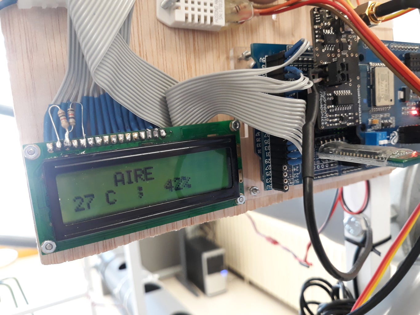
We integrated an LCD display in order to see all the sensor data without having to connect to the hydroponics cultivation wirelessly.
Step 15: Android APP


We created a specific application using App Inventor.
Here you can find the source file.
App procedure
- Receive and view data from the sensors.
- Send the current time of the mobile to update the time of the Arduino.
Step 16: Web Server

We connected the system to Thingspeak (a service that provides data storage and analysis) using an ESP8266 module.
Step 17: Hydroponic Working!
Finally! We created a working modular hydroponic system in our school! :)
Step 18: The Team

Team: Lanuza Makers
School: Juan de Lanuza
Activity: Robotics in family
Step 19: Resources

Here are some useful links. We hope this helps you design your own system. Feel free to leave questions or comments. Thanks!
Programming
- Arduino: https://www.arduino.cc/
- APP inventor: http://ai2.appinventor.mit.edu/
- Thingspeak: https://thingspeak.com/
Hydroponic in general

Grand Prize in the
Water Contest


