

Introduction: Remote Controlled 6WD All Terrain Robot


Most of the robots I built so far were 4 wheeled robots with a load capacity of several kilograms. This time I decided to build a bigger robot that will easily overcome various obstacles on its way and will be able to move with a load of at least a dozen kilos. I also assumed that the robot should be able to cope in difficult terrain such as sand, snow and rubble. To make it possible, I built a 6-wheel chassis equipped with 6 motors of sufficient high power and suitable motor driver and power supply. I also wanted my robot to be controlled from a long distance (at least 200 meters) so I used a good quality 2.4GHz transmitter and receiver.
Once all the above requirements were met and the first tests were successful, I decided to extend the project with a manipulator and two cameras. Thanks to the image from the camera you can control the robot even if it is out of sight. This feature allows the robot operator to perform remote inspection tasks in areas that are difficult to access or are dangerous for humans.
From the description of this project you will learn how to:
- build a 6 wheeled robot chassis capable of transporting at least a dozen kilos
- allows you to transport heavier items
- possible commercial use and not just a robot as a toy!
- remotely control such a robot from a long distance
- bind a 2.4 GHz transmitter with a receiver
- read commands from a 2.4 GHz receiver via Arduino
- control of the robot's position
- set preview from cameras on your computer or smartphone
- implementation of wireless long-range video transmission at 5.8 GHz
Robot parameters (basic version):
- External dimensions (LxWxH): 405x340x120 mm
- Total weight: 5 kg
- Ground clearance: 45 mm
Extended version (with a manipulator and a cameras):
- External dimensions (LxWxH): 405x340x220 mm (robot prepared for transport)
- Total weight: 6.5 kg
Step 1: The List of Parts and Materials

Chassis of the robot is made entirely from aluminum and duralumin. In this project I used 6 Monster Truck wheels with a diameter of 125 mm which makes it easy to overcome small obstacles. The robot is driven by 6 high-power 12 V brushed DC motors (180 RPM, 27 kg-cm) with metal gears. As a motor driver you can use any driver that is able to provide a continuous current of at least 10A per motor e.g.: VNH2SP30, BTS7960B.
Parts needed in this project:
- High Torque Gear Reducer DC Motor 12V 180RPM x6
- 6mm Hex DC Gear Motor Connector x6
- Emergency Stop Switch x1
- Stainless Steel Power Push Button Switch x2
- 7.4V 2700mAh 10C Lipo Battery x1
- 11.1V 5500mAh 3S 45C Lipo Battery x1
- Motor Driver e.g.: VNH2SP30 x6 or BTS7960B x2
- Arduino mega 2560 x1
- Wheel Rim & Tires HSP 1:10 Monster Truck x2
- Micro USB Board x1
Control:
Materials (chassis):
- Duralumin sheet 2mm thick (LxW): 345x190 mm x2
- L-shaped aluminum angle bracket 2mm thick: 190x40x20 mm x2
- C-shaped aluminum angle bracket 2mm thick: 341x40x20 mm x2
- Nuts and bolts:
- M3 10 mm x10
- M2 6 mm x8
Tools:
Extended version:
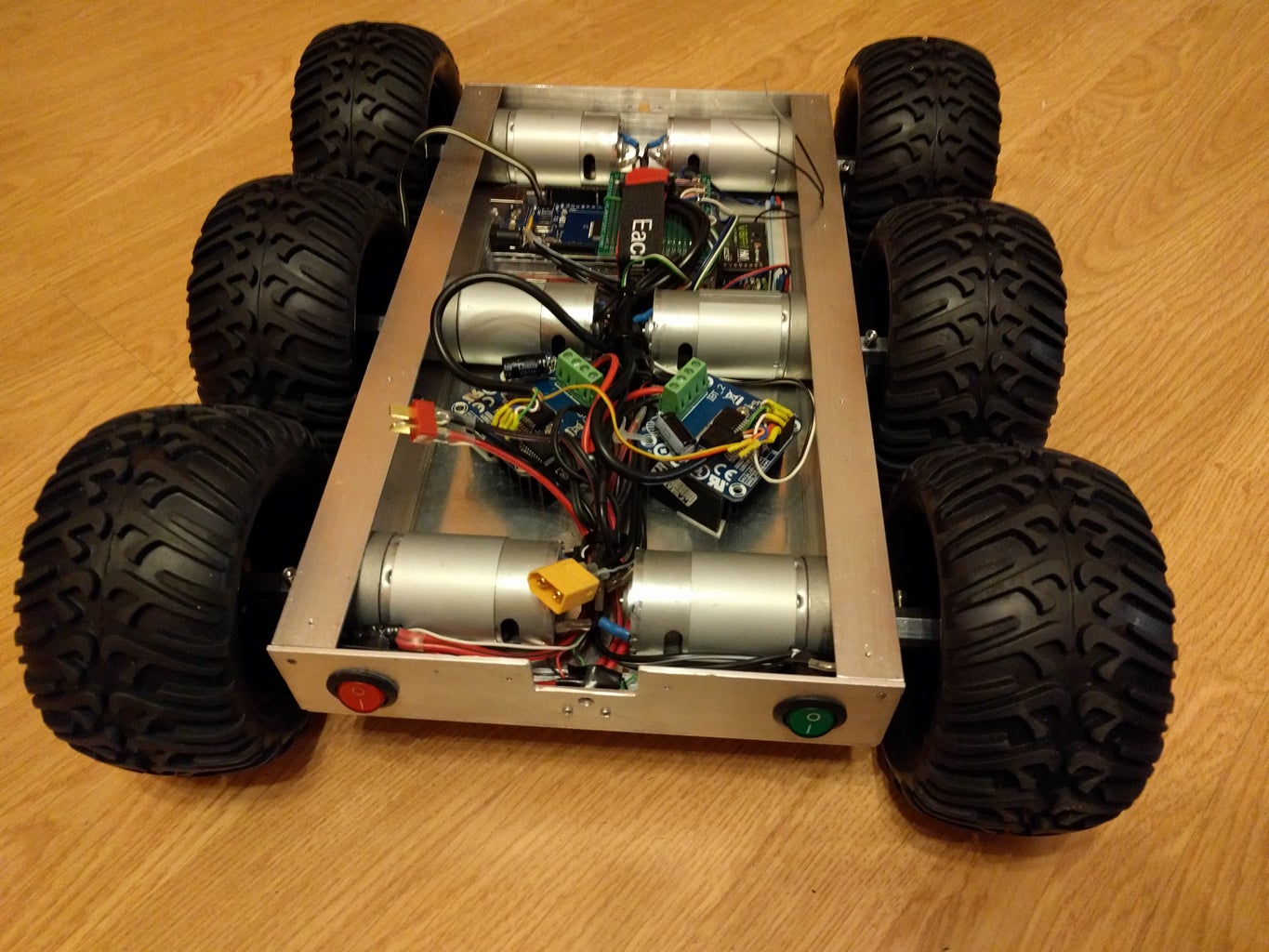
Step 2: Assembling the Robot Chassis


Assembling of robot chassis is quite easy. All steps are shown in the photos above. The order of the main operations is as follows:
- Drill 3 holes with a diameter of 13 mm in side aluminum profiles (Holes for the motor shaft)
- Drill 6 holes with a diameter of 3 mm in side aluminum profiles (Holes that fasten the motors to the profile)
- Screw the DC motors to the side aluminium profiles
- Screw the side aluminium profiles with DC motors to the base
- Screw the front and rear profile to the base
- Install the necessary power switches and other electronic component (see in the next section)
Step 3: Connection of Electronic Parts


The main controller in this electronic system is Arduino Mega 2560. To be able to control six motors I used two BTS7960B Motor Drivers (H-Bridges). Three motors on each side are connected to one motor driver. Each of the Motor Driver can be loaded by the current up to 43A that gives a sufficient margin of power even for the mobile robot moving over rough terrain. The electronic system is equipped with two power sources. One for supplying the DC motors and servos (LiPo battery 11.1V, 5500 mAh) and the other to supply Arduino, bluetooth module, fpv camera and sensors (LiPo battery 7.4V, 2700 mAh).
The connections of electronic modules are the following:
BTS7960 -> Arduino Mega 2560
- MotorRight_R_EN - 22
- MotorRight_L_EN - 23
- MotorLeft_R_EN - 26
- MotorLeft_L_EN - 27
- Rpwm1 - 2
- Lpwm1 - 3
- Rpwm2 - 4
- Lpwm2 - 5
- VCC - 5V
- GND - GND
FrSky V8FR-II 2.4GHz Receiver -> Arduino Mega 2560
- ch2 - 7 // Aileron
- ch3 - 8 // Elevator
- VCC - 5V
- GND - GND
The wired connections between the 2.4 GHz receiver and the Arduino are shown in the wiring diagram above. Connect the 5V and GND power wires from Arduino to the receiver's pins + (VCC) and - (GND) respectively. In addition, you must connect used receiver channels (ch2 and ch3) to the Arduino digital pins (e.g. 7 and 8 just like in the program). If you're just starting to learn electronics and you do not know how to connect power supply, switches and motor driver, this wiring diagram from my similar project will be helpful. Before starting the robot's control from the 2.4 GHz Taranis Q X7 2.4GHz transmitter you should previously bind the transmitter with the receiver. The binding procedure is described in detail in my video.
Step 4: Arduino Mega Code

I've prepared the following sample Arduino programs:
The first program "RC 2.4GHz Receiver Test" will allow you to easily start and check the 2.4 GHz receiver connected to Arduino, the second "6WD Robot Control" allows to control the robot's movement. Before compiling and uploading the sample program, make sure that you have chosen "Arduino Mega 2560" as the target platform as shown above (Arduino IDE -> Tools -> Board -> Arduino Mega or Mega 2560). The commands from Taranis Q X7 2.4 GHz transmitter are sent to the receiver. Channels 2 and 3 of the receiver are connected to the Arduino digital pins 7 and 8 respectively. In the Arduino standard library we can find function "pulseIn()" that returns the length of the pulse in microseconds.We will use it to read the PWM (Pulse Width Modulation) signal from the receiver which is proportional to the tilt of the transmitter's control stick. The pulseIn() function takes three arguments (pin, value and timeout):
- pin (int) - the number of the pin on which you want to read the pulse
- value (int) - type of pulse to read: either HIGH or LOW
- timeout (int) - optional number of microseconds to wait for the pulse to be completed
The read pulse length value is then mapped to a value between -255 and 255 that representing forward/backward ("moveValue") or turn right/left ("turnValue") speed. So, for example if we push the control stick fully forward we should get the "moveValue" = 255 and pushing fully back get "moveValue" = -255. Thanks to this type of control, we can regulate the speed of the robot's movement in the full range.
Step 5: Testing of Mobile Robot

These videos show tests of mobile robot based on program from the previous section (Arduino Mega Code). The first video shows tests of 6WD robot in my room. This robot is able to carry a load of several kilos very easily, on the video it transports 8 bottles of water equivalent to 12 kg. The robot can also easily overcome obstacles encountered on its way like curbs on parking what you can see in the second video. At the beginning of this instruction you can also see how well it cope in difficult terrain.
Step 6: Examples of Design Improvements

You can extend this project with additional components such as:
- robot gripper
- robotic arm (described in this instruction)
- gimbal with a camera
Above you will find two videos presenting the mentioned improvements. The first video shows how to control a pan-tilt camera and a robot gripper using Taranis Q X7 2.4GHz transmitter and FrSky V8FR-II receiver. Next video shows a quick introduction how to connect and control a 2 axis gimbal using the same set of transmitter and receiver at 2.4 GHz.
Step 7: Robot Arm Tuning


I made the robot arm earlier and described it in this instruction. However, I decided to slightly modify the original project and add another degree of freedom (wirst) and FPV camera. The robot currently has 4 rotary joints:
- Wirst
- Elbow
- Shoulder
- Base
Rotation in 4 axes allows easy gripping and manipulation of objects in the robot's workspace. A rotating gripper that performs the role of the wrist allows you to pick up objects placed at different angles. It was made of the following parts:
- LF 20MG 20 KG Digital Servo x1
- Servo Bracket x1
- Duralumin cylinder with a thickness of 4 mm and a diameter of 50 mm
- Duralumin sheet 36x44 mm and thickness of 2 mm
- Bolts and nuts M3 x4
- FPV camera - RunCam OWL Plus x1
The camera is placed directly above the gripper to make it easier for the operator to grab even small objects.
Step 8: Checking the Status of the Robot and Preparing for Transport


The robot arm and camera stand are folded, that makes the robot transport much simpler. The rear panel of the robot is equipped with 3 LEDs. Two of them show the power status of electronics, motors and servos (on or off). The third RGB LED shows the battery status and failure. For easier programming, the robot is equipped with a micro USB port. This solution makes testing much easier without the need to remove the robot housing.
Step 9: Testing Preview From Wifi and Fpv Cameras

Two cameras were installed on the robot. The Wifi camera was placed on an adjustable aluminum holder at the back of the robot. A small fpv camera was placed just above the robot gripper.
Cameras used in this test:
- RunCam OWL Plus
- XiaoMi YI Wifi camera
The first video shows the test of both cameras. The view from the wifi camera is displayed on the smartphone and the view from the fpv camera on the laptop. As we can see on the video, the preview delay is small and for Wifi camera this delay is slightly larger.
In the second video, I showed you step by step how to get a preview from 5.8 GHz fpv camera on your computer. The image from the camera is sent from the transmitter to the 5.8 GHz receiver. Then it goes to a video grabber connected to a laptop via a usb port and is finally displayed on the VLC player.
Check out my other projects related to robotics, just visit:
Step 10: Image Processing and Possible Practical Applications
Currently I'm developing a dedicated application for 6WD security vehicle. This app providing the following functionality:
- preview and record the image in real time
- snapshots
- detecting moving objects
- objects tracking
- marking detection zones
- automatic sending of alarm notifications
I'm using Python, OpenCV and TensorFlow when creating and testing this software.
Examples of applications:
- protection of facilities and areas against the access of unauthorized persons
- exploration and inspection of hard to reach places
- tunnels and pipes
- inspection of dangerous places for human life and health
- chemically contaminated places
- buildings threatening to collapse
- transport and neutralization of dangerous objects (explosives, harmful and toxic chemicals)
Example problem and its solution
Formulation of the problem:
Currently a classic monitoring and protection system use of stationary cameras that monitor only the part of the area that should be protected. This disadvantage causes that the system is incomplete and provides only partial control over what is happening in the protected area. Additionally, the camera itself usually does not have the ability to monitor environmental parameters.
Solution to the problem:
The solution to the problem formulated above is a camera placed on a remotely controlled or autonomous vehicle. Such a vehicle can reach every corner of a protected area and give us a real-time preview if everything is okay. It can also send measurement data of physical quantities (e.g. gases, temperatures) to the base station. Furthermore, the transmitted image is processed to detect moving objects with specific features in the selected protected zone. If such objects appear then the system will send an emergency notification to the owner or security office.

Second Prize in the
Remote Control Contest 2017

Second Prize in the
Wheels Contest 2017

Participated in the
Arduino Contest 2017


