

Introduction: Selecting the Right Sensor for Arduino Projects


There are many types of sensors available that enable you to interact with electronics, and so it can be difficult to decide which one is best to use for a project. Furthermore, many tutorials show how to use a single sensor with an Arduino, but it can be unclear how to use lots of them in a project that requires lots of detectors (e.g. laser harps, interactive LED tables, etc.). In this instructable, I will review some sensors (listed below) and focus on how to use them with an Arduino. In addition to the review, I will provide some pros and cons for using each one of these sensor types in Arduino projects that require lots of sensors and explain what to do when there are more sensors than there are pins on the Arduino. Hopefully, this instructable will help you pick the best sensor for your project and understand how to wire many of them up so that they can be used with an Arduino.
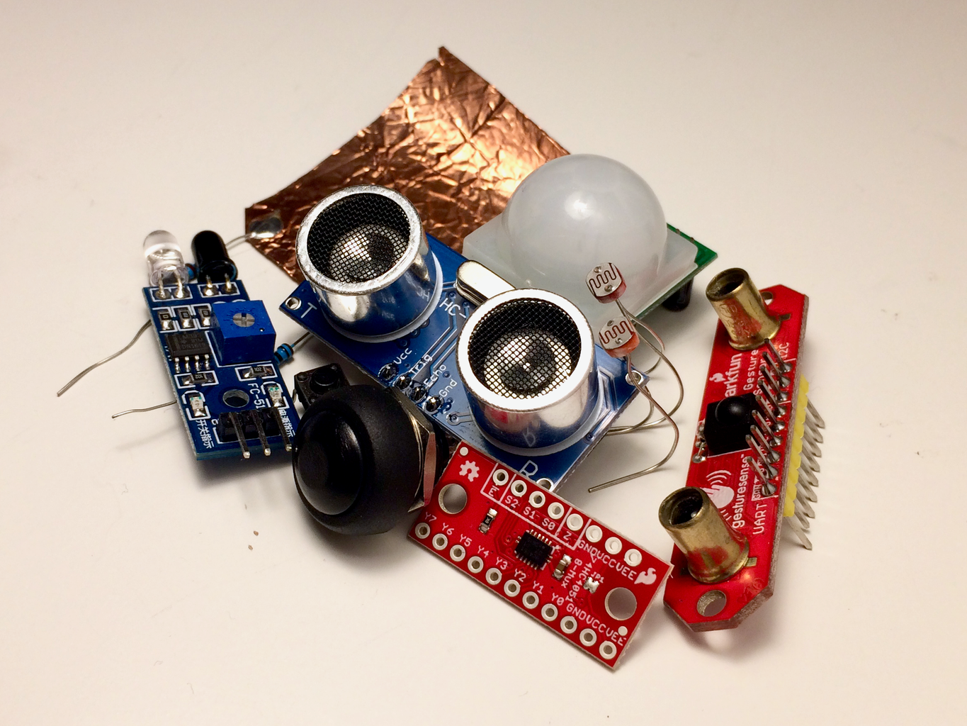
List of detectors in this review:
Push buttons
IR sensors (Active and passive)
Photodetectors (Photoresistors and phototransistors and photodiodes)
Ultrasonic sensors
Capacitive touch sensing
Step 1: Push Buttons and Switches


The easiest way to provide someone a way to interact with an electronic device is by using a pushbutton or switch. A switch usually clicks into a position so that a person can click it back and forth, while a pushbutton goes down when pressed and springs back up. The idea is to create a circuit with a pushbutton or switch connected to a resistor, and readout the voltage at the node between the resistor and 5V. The resistor is required so that the circuit is not shorted when the button is pressed.
If the switch or button is not closed, then the readout above the resistor will be zero volts, which is also written as LOW or simply 0. If the switch or button or pressed, the circuit is completed and current will flow, which results in a 5 volt readout above the resistor, which is also written as HIGH or simply 1. Therefore, the switch or pushpin is said to be a digital read, meaning it can be only one of two values.
For an electronics project that requires a lot of two state inputs, switches and pushpins can be a great solution. It is easy to tell when the switch is on or off, and the signals between different switches don’t interact (i.e. there is no cross-talk). It is also relatively easy to build your own pushbuttons with conductive material if you want to customize them to a device that you are making or don’t want cheap pushbuttons to be visible. See links below for custom switches people have made. You can read in as many switches you have digital pins on the Arduino by putting the switches in parallel (see diagram). Attached is code for reading switches with an Arduino. If you need more inputs, then you can multiplex (see the step 6).
Pros: Clear signal. Reliable. No crosstalk between detectors. Simple to wire. Cheap. Relatively easy to make a custom switch or pushpin.
Cons: Don’t detect motion, person must physically touch sensor. Digital readout only.
Push button tutorial: https://www.arduino.cc/en/Tutorial/Button
Attachments

Step 2: Infrared Sensors


Infrared (IR) radiation is a form of light with longer waves that is typically not visible to the human eye. IR radiation has the energy of vibrational transitions in molecules, so it is often associated with heat generated by living organisms (imagine IR cameras). In other words, the warmer an object the more IR radiation is emitted from the object.
An IR sensor detects IR radiation in one of two ways. A passive IR sensor consists of only an IR detector. Therefore, it detects the IR radiation emitted from objects, and is useful for detecting the difference between objects of different temperature, like a human entering someone’s yard. An active IR sensor consists of both an IR emitter and an IR detector. The emitted IR radiation of an active IR sensor is reflected off of any object and then detected by the IR detector on the sensor. Therefore, active IR sensors are good at detecting an object that passes by the sensor, and usually have better signal quality in comparison to passive IR sensors.
For using lots of IR sensors in a single electronic device, it makes more sense to use an active IR sensor because passive IR sensors have a very large detection range and have much worse signal. This makes it difficult to decipher much of a difference from different passive IR sensors close to each other.
It is possible to assemble your own active IR sensor with an Arduino as shown in ricardouvina’s instructable. The sensor requires IR LEDs, an IR diode receiver, and resistors. Working through this instructable is a great way to learn how an active sensor works and the output signal that is generated. The nice part about this approach is that the output is an analog signal that corresponds to the amount of IR radiation detected by the sensor, which usually represents the distance an object is from the sensor. Therefore, you can use this information to make an electronic device behave differently depending on how close the object is to the sensor. Ricardouvina’s instructable demonstrates this with a buzzer.
The downside to building your own IR sensor is that it takes a lot of time. Instead you can buy a completely constructed IR sensor with either an analog or digital output. The analog IR sensors are generally more expensive, but they give you distance information. The digital IR sensors are cheaper, but they only tell you whether or not the sensor is blocked. A trimpot on the sensor is used to adjust the sensitivity of the digital IR sensors. There are even more sophisticated IR sensors that encode distance, as well as the velocity and direction of certain gestures.
How well do IR sensors work for projects requiring a lot of sensors? If you just want to track objects over a large area with lots of sensors, then the best IR sensor to use is probably a digital active IR sensor. Analog IR sensors, especially gesture sensors, are more complicated, more expensive, and require more time to process information than the digital active IR sensors. They may also be noisier than you think, and to get a precise measurement with them you will probably need to average measurements, which takes time and will slow down your device if you are using a lot of sensors.
Pros: Digital active IR sensors are cheap. Detection without touching the sensor. Analog IR sensors provide object distance information.
Cons: Will take time to build a lot by hand. Analog IR sensors are more expensive. A lot of IR sensors will be difficult to calibration. Noisier signal. Can be cross talk from IR radiation emitted by other sensors or surrounding IR radiation.
Analog active IR sensor (i.e. a distance sensor): https://www.adafruit.com/product/164?gclid=Cj0KCQj...
Digital active IR sensor: https://www.ebay.com/p/5pcs-IR-Infrared-Obstacle-A...
Gesture sensor: https://www.sparkfun.com/products/13162
How to use a passive sensor: https://learn.adafruit.com/pir-passive-infrared-pr...
Long distance IR sensor: https://www.adafruit.com/product/1568
Step 3: Photodetectors


Photodectors are electrical sensors that measure changes in light. Therefore, if a person somehow alters the amount of light reaching the sensor, then the signal produced by the photodetector can be used to control another electrical component. One example of this is a laser harp. The amount of light measured by the photodetector changes depending on whether or not the person blocks a laser beam.
Photoresistors, photodiodes, and phototransistors are all examples of photodetectors. For a great tutorial on these components, check out this link. The big difference between them is that photoresistors have a much slower response time to changes in light than photodiodes and photoresistors. The sensitivity of each of these sensors can be adjusted by changing the resistors in the circuit. For example, if you place a lower resistance in parallel with a photoresistor, then you will be able to measure changes of very bright light sources. If you instead use a higher resistor, then you will be able to measure changes in low light situations.
To use a photoresistor, connect the photoresistor in series with another resistor (see diagram). The signal is read from the node between these components. Connect a wire from this node to an analog pin. Attached is the code for using a single photoresistor.
There are analog devices, so one of the changes in using them is that you will have to calibrate and use an analog channel on the Arduino. Because there are only 6 analog input channels, you have to use a multiplexer if you want to use more than 6 photodetectors in a device (see Step 6). Another challenge for using these detectors is that you need to put thought into how to design the circuit so that it is sensitive only to the light intensity changes you wish to detect. You may have inconsistent measurements when you move the device to locations with different lighting. Therefore, it is helpful to use a constant high intensity light source, like a laser, that can be blocked by the user. There is still a possibility that ambient light will interfere with the differentiation of a blocked vs. non-blocked beam.
Pros: Detection without touching sensor. Works well with laser beams. Analog output can be used to encode distance information. Sensitivity of sensor can be adjusted easily by changing resistors. Works well with lasers or pulsed light sources.
Cons: Ambient light conditions can distort signals. Constant light source is likely required for robust detection. Only a few analog input on board, so multiplexing required when using lots of photodetectors.
Photoresistors – 10ms
Photodiodes – 1µs
Phototransistors – 15µs
Comparison of photoresistors, photodiodes, and phototransistors: https://www.youtube.com/watch?v=DNAgJrnj4EM
Laser harp: https://www.instructables.com/id/13-Note-MIDI-Laser-Harp-Controlled-by-Arduino/
Attachments
Step 4: Ultrasonic Sensors
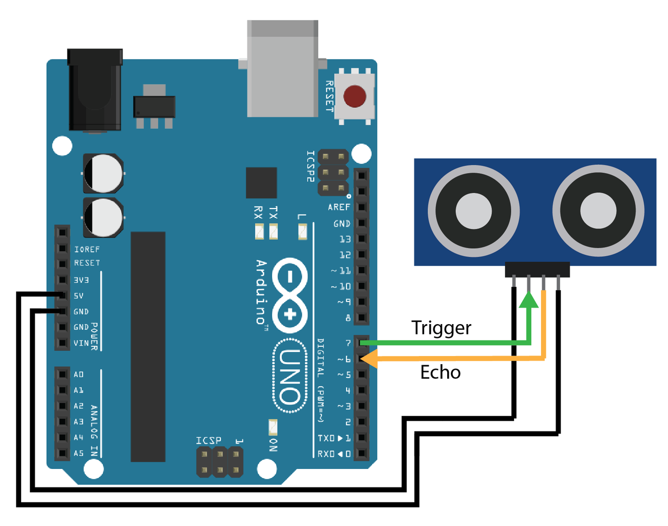

Ultrasonic sensors are conceptually similar to IR sensors, but instead emit and receiver ultrasonic waves. A trigger pin sends a signal to produce an ultrasonic pulse, and the echo pin generates a signal depending on an ultrasonic wave that is detected by the receiver. If something passes by the sensor, ultrasonic waves are reflected off the object and detected by the ultrasonic receiver.
The amount of time between when the ultrasonic pulse is produced and when it is detected depends on the distance the object is from the sensor. Therefore, a major benefit of ultrasonic sensors is that they provide distance information about near by objects. Ultrasonic sensors provide non-contact detection for distances ranging from 2cm to 500cm, which is generally greater than the range of IR sensors. They also have a tight beam angle (around 10°-15°) so their detection can be sensitive to only a small area. For reference, the passive IR sensors have detector angles of >100°.
To use the ultrasonic sensor, the echo and trigger pins are connected to two pins on the Arduino. Attached is code for sending ultrasonic pulses and receiving them with the sensor. When I started using these sensors, I was disappointed with the performance so I did some searching and found the newPing library. It’s a library that helps improve some of the issues with using these sensors. There’s even an example for using 15 sensors.
Even with this library, I still had issues with using 16 of these sensors for the laser sheet project I did. In general, the sensors were noisy and therefore required long sampling times and averaging, which lowered the update rate of the device. Furthermore, the amount of time per read on the sensor depended on the echo time so it appeared as though the device was running faster or slower depending on what the user was doing. In the end, I had to set the max distance read for the sensors to only 20cm, which defeated the purpose of using these sensors for long distance reads.
Pros: Long distance readings. Non-contact detection. Narrow detection range.
Cons: Noisy sensors. Variable speed on reads from sensor. Speed may be an issue when using lots of sensors because average required.
Ultrasonic sensor tutorial: http://howtomechatronics.com/tutorials/arduino/ult...
New Ping library: http://playground.arduino.cc/Code/NewPing
Laser sheet project: https://www.instructables.com/id/Interactive-Laser-Sheet-Generator-With-Arduino/
Step 5: Capacitive Touch


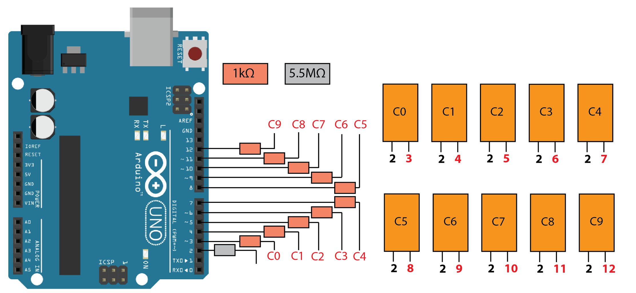

Capacitive touch sensors consist of two resistors and a conductive material like copper sheet. A large resistor (e.g. 5MOhm) is connected to the conductive material that acts as one plate in a capacitor. A person’s hand then acts as the other side of the capacitor with his/her body considered to be connected to ground. An electrical pulse is sent out from one pin and another pin waits to receive the pulse. The time it takes for the pin to receive the pulse depends on the capacitance in the circuit. As a person touches the sensor more, the capacitance increases, delaying the time for the pulse to be received by the receive pin (See diagram). I have code for using a single sensor, as well as code for hooking up ten capacitive sensors to an Arduino and storing their output in an array (diagram also shown).
The sensitivity of the sensor can be adjusted by changing the resistance. It can even be possible to record changes in the signal without touching the sensor. You can also place things between the conductive material and your hand to hide the copper plate or to make everyday objects into touch sensors. Even though you are using a digital pin with these sensors, you still get analog-type signals because it is a measurement of a time delay, not whether or not the pin is high or low.
Pros: Great signal, with or without an object between the plates. Customizable. Analog-type reading with digital pin. Minimal crosstalk (can probably be improved with better shielding too).
Cons: Read time can slow down depending on capacitance. Contact with sensor is essentially required.
Library: https://hackaday.com/2011/11/21/simple-touch-sens... OR http://playground.arduino.cc/Main/CapacitiveSensor
Great capacitive touch video: https://www.youtube.com/watch?v=BHQPqQ_5ulc
Cap touch music: https://www.youtube.com/watch?v=Wk76UPRAVxI
Attachments
Step 6: How to Use Many Sensors: Multiplexing


There are some projects that require more sensors than there are pins on the Arduino, especially if you are using analog sensors because there are much fewer analog pins than digital pins. One solution is to use a bigger microcontroller, like the Arduino Mega. However, there may be some cases that you want to sick to a smaller microcontroller. If so, then you will have to use a multiplexer. I have used multiplexers for my laser harp project, which required 13 analog signals to be read into an Arduino) and dome project (which required 120 digital signals to be read into an Arduino).
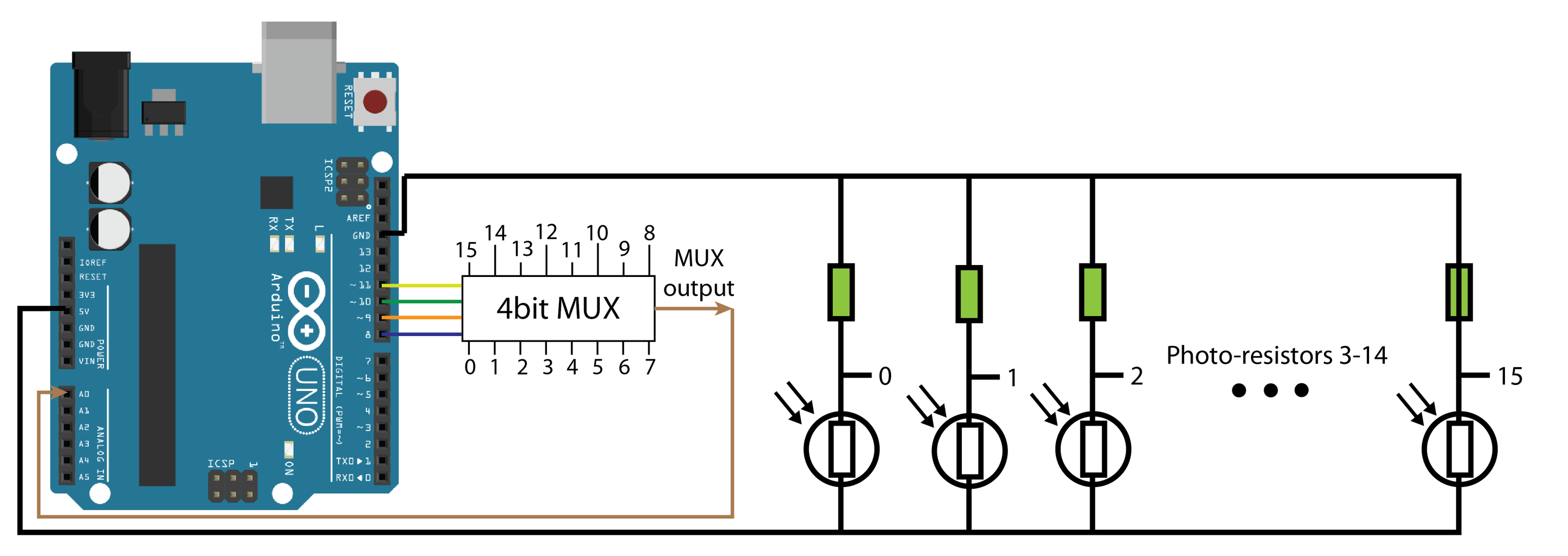
A multiplexer is an electrical device that takes in many signals, and allows one to pass at a time. The signal that passes is determined by a digital control signal sent to the device. For example a 16 channel multiplexer has for control signals that together can produce 16 combinations. Check out the figure for an example displaying the control signals and which channel is passed.
To set up a 16 channel multiplexer, connect the control signals to pins 8-11 of the Arduino. Then connect the output of your 16 sensors to the channel pins on the multiplexer. Finally connect the signal pin to a digital or analog input on the Arduino. The code attached here shows how to increment pins 8-11 using serial communication with the Arduino.
16 channel MUX breakout board: https://www.sparkfun.com/products/9056
8 channel MUX breakout board: https://www.sparkfun.com/products/13906
Pin headers: https://www.amazon.com/gp/product/B00U8OCENY/ref=o...
Step 7: Comparison of Sensors


Hopefully this overview of sensors will help you pick the best one for your next project. Check out the table for a summary of the pros and cons of all these sensors above.


